7
EN
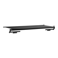
Slide Topper Pre-Installation
Ref. Bracket Position
Extension
Position
Dimension
Specifications
(X) (Y)
A Tall Standard Standard 1.79 in.
(4.5 cm)
5.33 in.
(13.5 cm)
B Tall Standard Inverted 1.83 in.
(4.6 cm)
5.70 in.
(14.5 cm)
C Short Standard Standard 1.21 in.
(3.1 cm)
4.01 in.
(10 cm)
D Short Standard Inverted 1.21 in.
(3.1 cm)
4.38 in.
(11 cm)
E Tall Inverted Standard 1.02 in.
(2.6 cm)
2.91 in.
(7.4 cm)
F Tall Inverted Inverted 0.98 in.
(2.5 cm)
3.27 in.
(8.3 cm)
G Short Inverted Standard 1.21 in.
(3.1 cm)
4.26 in.
(11 cm)
H Short Inverted Inverted 1.21 in.
(3.1 cm)
4.63 in.
(12 cm)
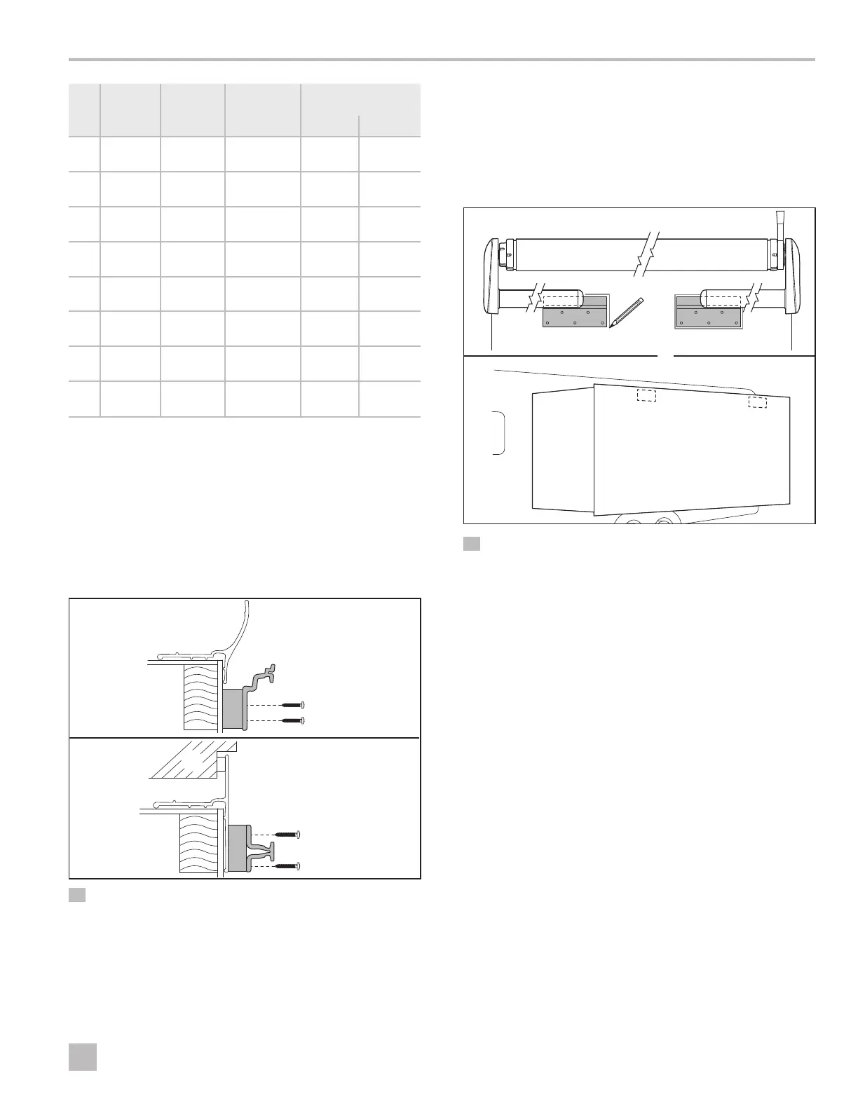
3.4 Using an Optional Mounting
Bracket Spacer
When the RV slide-out room flange has special features
like a large curve, or the flange is recessed into the RV
wall, use a mounting bracket spacer (not included).
I
The mounting bracket spacer thickness may vary
depending on the spacer kit requirements.
q
q
r
w
e
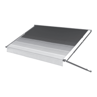
4 Optional Mounting Bracket Spacer
q
0.5 in. or 0.75 in. (1.3 cm or
2.0 cm) Mounting Bracket
Spacer (size may vary)
e
RV Wall
w
Large Curve in Flange
r
Recessed Flange
3.5 Marking the Mounting Bracket
Location
Use this section to mark the location of the mounting
brackets that were selected for the installation of the
Slide Topper.
q
w
e
w
w
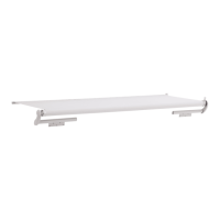
5 Mounting Brackets
q
Fabric Roller Tube
Assembly
e
Slide-Out Room
w
Mounting Bracket
1. Find a solid structure in the RV slide-out room wall for
support of the mounting brackets.
2. Mark the spacing for the mounting brackets. The
spacing should be centered on the RV slide-out room.