ENGLISH
9
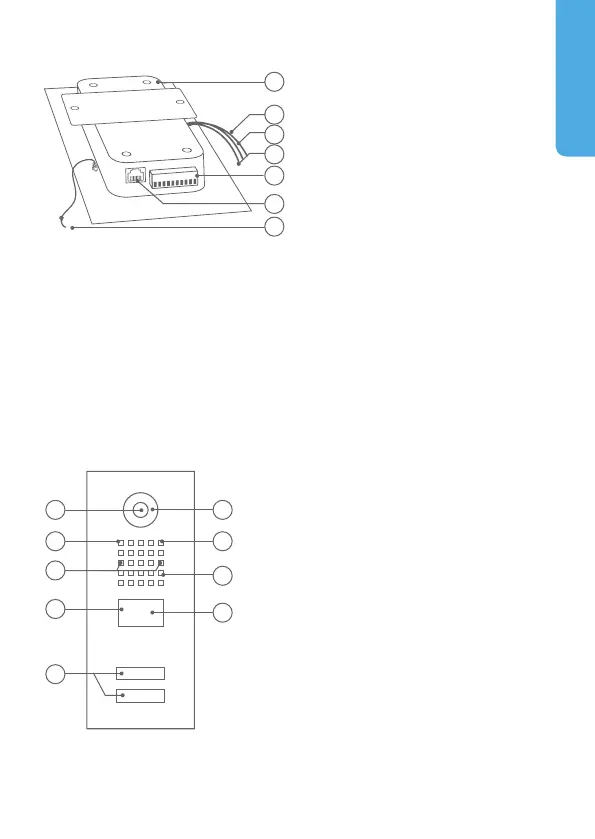
1) Main Electrical Unit
2) Yellow cable for call button
Connected to the illuminated call
button with nameplate
3) Red cable for Module Port 1
(unused)
4) Green cable for Module Port 2
(unused)
5) Screw connection terminal
6) LAN/PoE jack
7) Nylon cord
To secure the front panel during
assembly
Inside
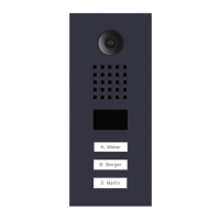
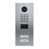
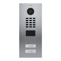
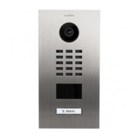
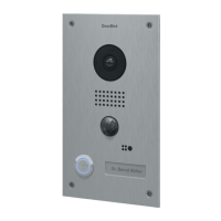
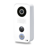
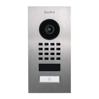
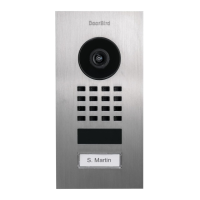
DEVICE EXAMPLE WITH AND MORE CALL BUTTONS
Front
1) HDTV Video
2) Light Sensor
For night-vision mode
3) Security screws
4) Motion Sensor
5) Illuminated call buttons
with nameplate
The illumination is also acting
as Diagnostic LED(s).
6) Night Vision LEDs
7) Microphone
8) Loudspeaker
9) RFID Reader
1 6
2 7
3
8
4
9
5
5
6
7
1
2
3
4