8
CONTROL UNIT DIAGRAM
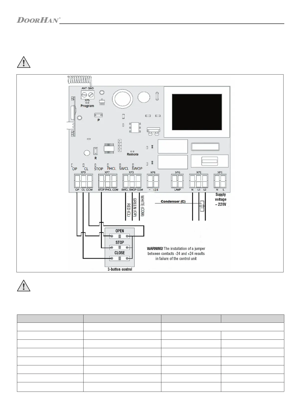
1. CONTROL UNIT DIAGRAM
1.1. CONTROL UNIT SCHEMATIC DIAGRAM
CAUTION! Wires in the cable shall be protected against contact with any rough and sharp parts. All connections shall be
performed only when the power is off.
CAUTION! If no devices are connected to PH CL and COM terminal, it is necessary to install a jumper between contacts
PH CL and COM.
Control unit LEDs
LEDs in bold type indicate the state when the door is stopped in the middle position.
LED Function On Off
Program the operation mode is selected
flashes according to the selected mode of operation
SW OP limit switch to open
does not respond
responds
SW CL limit switch to close
does not respond
responds
OP OPEN command on
off
CL CLOSE command on
off
PH CL photocells to close
do not respond
respond
STOP STOP command
off
on
Remote record of remote controller code on
off
 Loading...