9
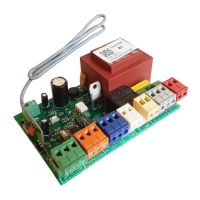
CONTROL UNIT DIAGRAM
1.2. CONTROL UNIT TERMINALS DESCRIPTION
Type Color Jack
Terminals
Connecting devices
№ Meaning
Control devices
GREEN
ХP9
1 Open
Full opening command. After closing of contacts of the device connected
to this terminal, the control unit will trigger either full opening of the door or
stepped control of operator (depending on the preset control logic)
2 Close
Close command. After closing of contacts of the device connected to this
terminal, the control unit will trigger door closing
3 Com Common contact
Safety devices
ORANGE
ХP7
1 STOP
Stop command. After breaking of contacts of the device connected to this
terminal, the control unit will stop door movement
2 PH CL
Contacts for safety device connection (NC). Safety devices are used to
prevent people, animals and foreign objects from being jammed in the door
opening by the moving door leaf. Activation of safety devices immediately
stops or reverses the door. If sensors of the safety devices responded when
the door was open, that will prevent any movement of the door
3 COM Common contact
Connection of end
switches
BLUE
ХP3
1 SW CL
Terminal for connecting of end switch which is responsible for extreme
position to closing on cloth (red wire from end switch)
2 SW OP
Terminal for connecting of end switch which is responsible for extreme
position to opening on cloth (green wire from end switch)
3 COM Common contact (white wire from end switch)
Contacts of
accessories
power
WHITE
ХP8
1 (–)
For accessories power supply
2 +24
Additional
accessories
YELLOW
ХP6
1
LAMP
Terminals for connecting of signaling lamp ~ 220 V. This split is only
present on board of version 1.1
2
Power of
motor
GREY
ХP2
1 N common terminal of electromotor
2 L1 terminal on closing of electromotor
3 L2 terminal on opening of electromotor
Power of
board
RED
ХP1
1 N
connecting of mains supply ~ 220 V
2 L
 Loading...