Power Train Disassembly & Assembly
a. Remove the drive pinion and bearing cage from
the carrier. Refer to the procedure on page 14.
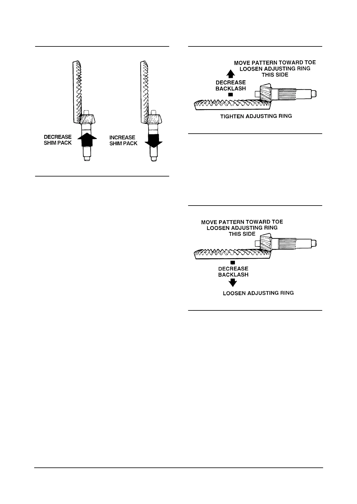
b. To correct a high contact pattern, decrease the
thickness of the shim pack under the bearing
cage. When decreasing the thickness of the shim
pack, the drive pinion will move toward the ring
gear.
To correct a low contact pattern, increase the
thickness of shim pack under the bearing cage.
When increasing the thickness of the shim pack,
the drive pinion will move away from the ring gear.
c. Install the drive pinion, bearing cage and shims
into the carrier, Refer to the procedure on page 24.
d. Repeat steps 2-5 until the contact patterns are in
the center between the top and bottom of the gear
teeth.
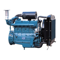
6. Adjust backlash of the ring gear within
specification range to move the contact patterns to
the correct location in the length of the gear teeth.
Refer to the procedure on page 36.
a. Decrease backlash to move the contact patterns
toward the toe of the ring gear teeth.
b. Increase backlash to move the contact patterns
toward the heel of the ring gear teeth.
c. Repeat steps 2-4 and 6 until the contact patterns
are at the correct location in the length of the gear
teeth.
7. Install cotter keys that hold the two bearing
adjusting rings in poistion. Use the following
procedures.
40