Vehicle System
Disassembly & Assembly 33
Attachment Carriage
If the lift truck is equipped with a sideshifter carriage,
an extra valve spool is installed in the control valve.
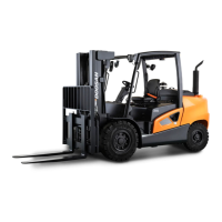
Sideshifter Carriage
(1) Sideshifter cylinder.
When the valve spool is moved to extend or retract
sideshifter cylinder (1), oil flows through the lines to
and from the control valve openings to move the
cylinder piston and rod. The cylinder moves the
carriage, either to the right or to the left. Sideshift
hydraulic circuit has the same pressure relief valve
as tilt circuit for protection against an overload. A
check valve prevents pressure oil through the
pressure outlet opening of the control valve from
returning under any circumstance.
Lift Cylinder and Mast
The rods of lift cylinders (4) are moved up by
hydraulic oil pressure and returned to their original
position by gravity.
The single action of pilot lift cylinders together with
other mechanical lifting components will operate as
follows:
When the lift lever of pilot control valve is pulled
back, the hydraulic oil pressure pushes against the
inner pistons at the bottom of the lift cylinders.
Inner mast (2) start to move up.
At the same time, carriage (3) also starts to move up
because it is connected to chains (5). Carriage (3)
moves at 2:1 ratio with the rods of the lift cylinders.
This movement of inner mast (2) and carriage (3)
goes on until lift cylinders (4) are at the end of their
stroke.
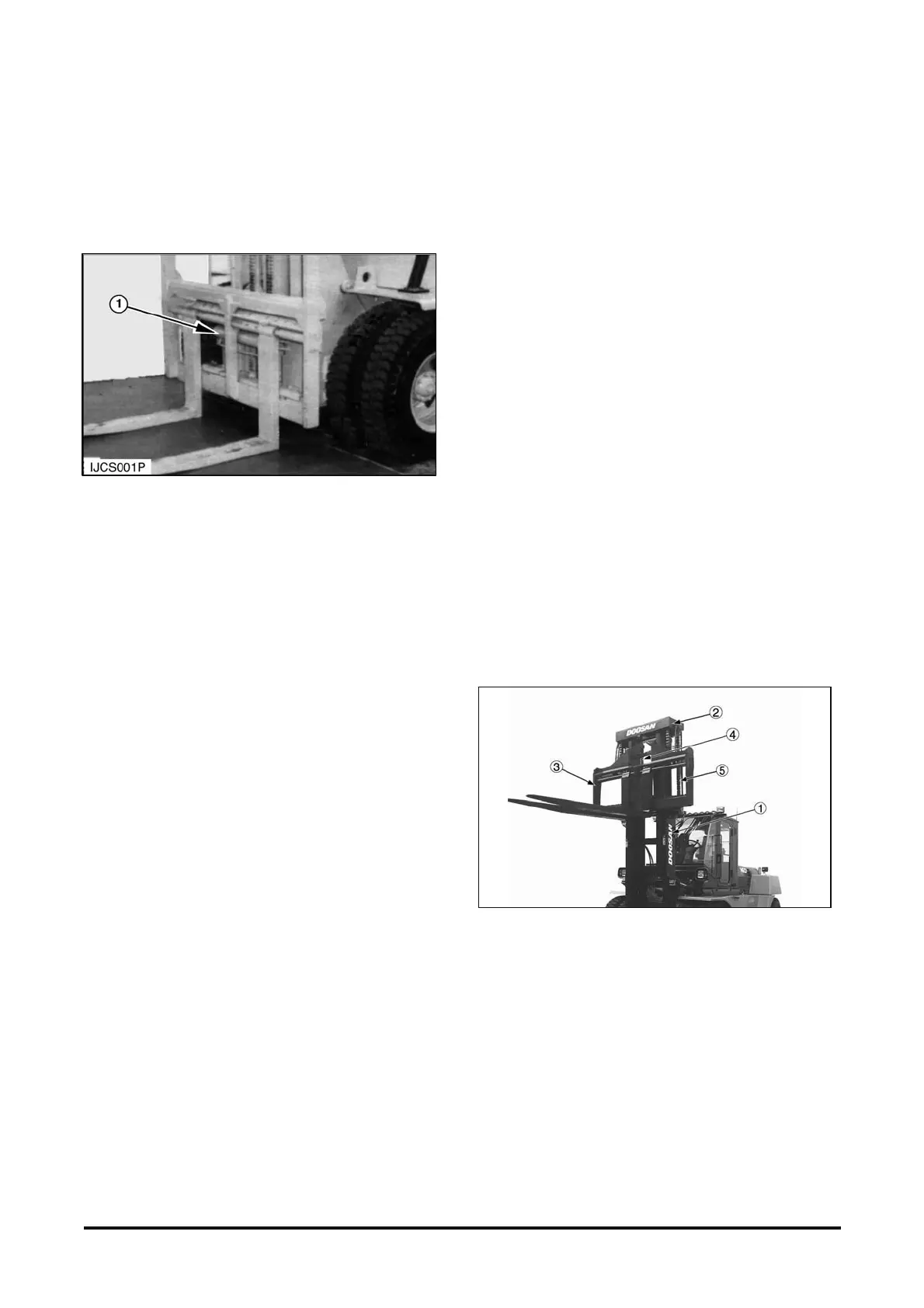
Lift Component
(1) Stationary mast. (2) Inner mast. (3) Carriage. (4) Lift cylinders.
(5) Lift chains.
 Loading...