5. About the engine
95
20. Attatch the fuel injection pump driven gear.
DV2213187A
1) Tighten 3 M8 fixing bolts(A) of the fuel injection pump
driven gear at a tightening torque 3.1 kgf·m ± 0.46kgf·m.
2) Rotate the fuel injection pump driven gear 360° with
rotating flywheel.
3) Tighten 3 the other M8 fixing bolts(A) of the fuel injection
pump driven gear at a tightening torque 3.1 kgf·m ±
0.46kgf·m.
21. Attach the flywheel housing cover.
DV2213188A
1) Attach the flywheel housing cover(A).
2) Tighten 4 M8 fixing bolts(B) at a tightening torque 2.2
kgf·m ± 0.3kgf·m.
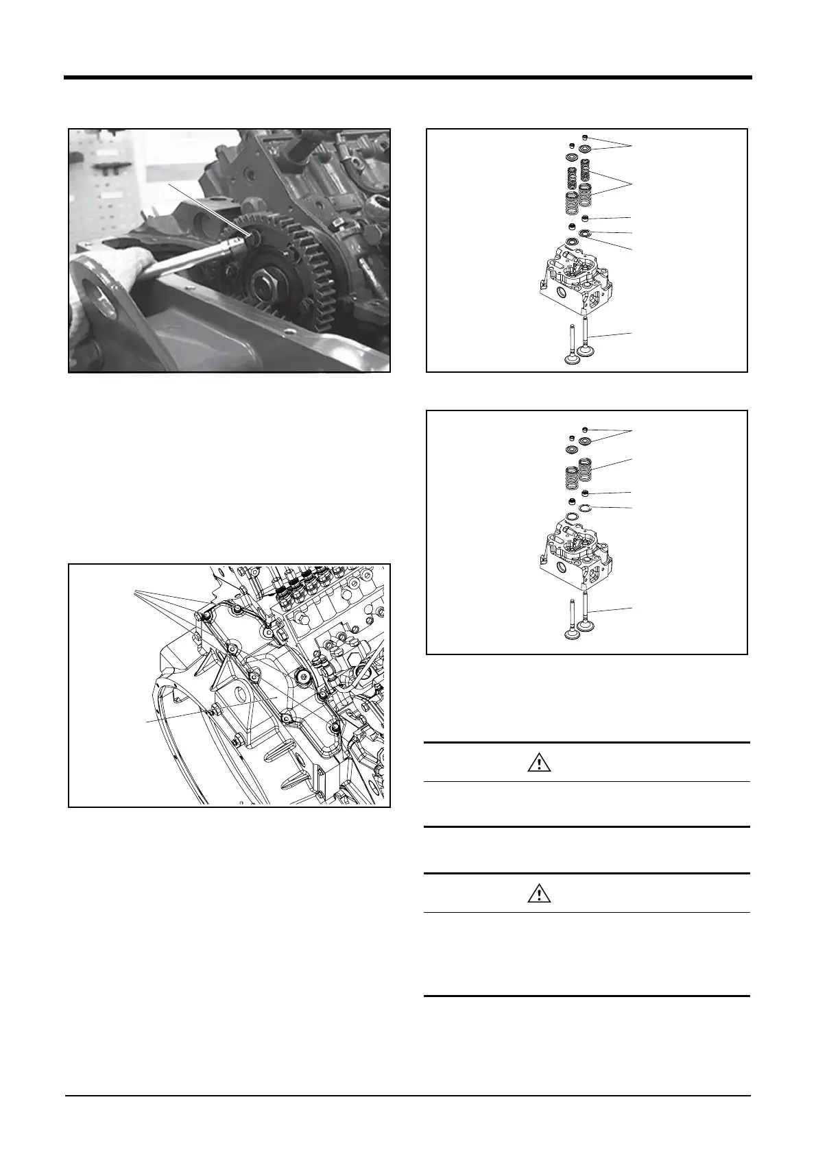
22. Attach the cylinder head.
DV2213189A
EDV2218001
1) Attach the outer washer(D).
2) Attach the valve stem seal(A) with the valve stem seal
punch(EF.120-183).
3) Attach the vavle(B).
Do not give an excessive shock on the valve stem
seals; otherwise, they may be damaged.
Be careful to use the right valve without confusing the
intake valve with the exhaust valve. The intake valve is
the mark “ I ” engraved on the head and the exhaust
valve is the mark “ E ” engraved on the head.