- 32 -
7
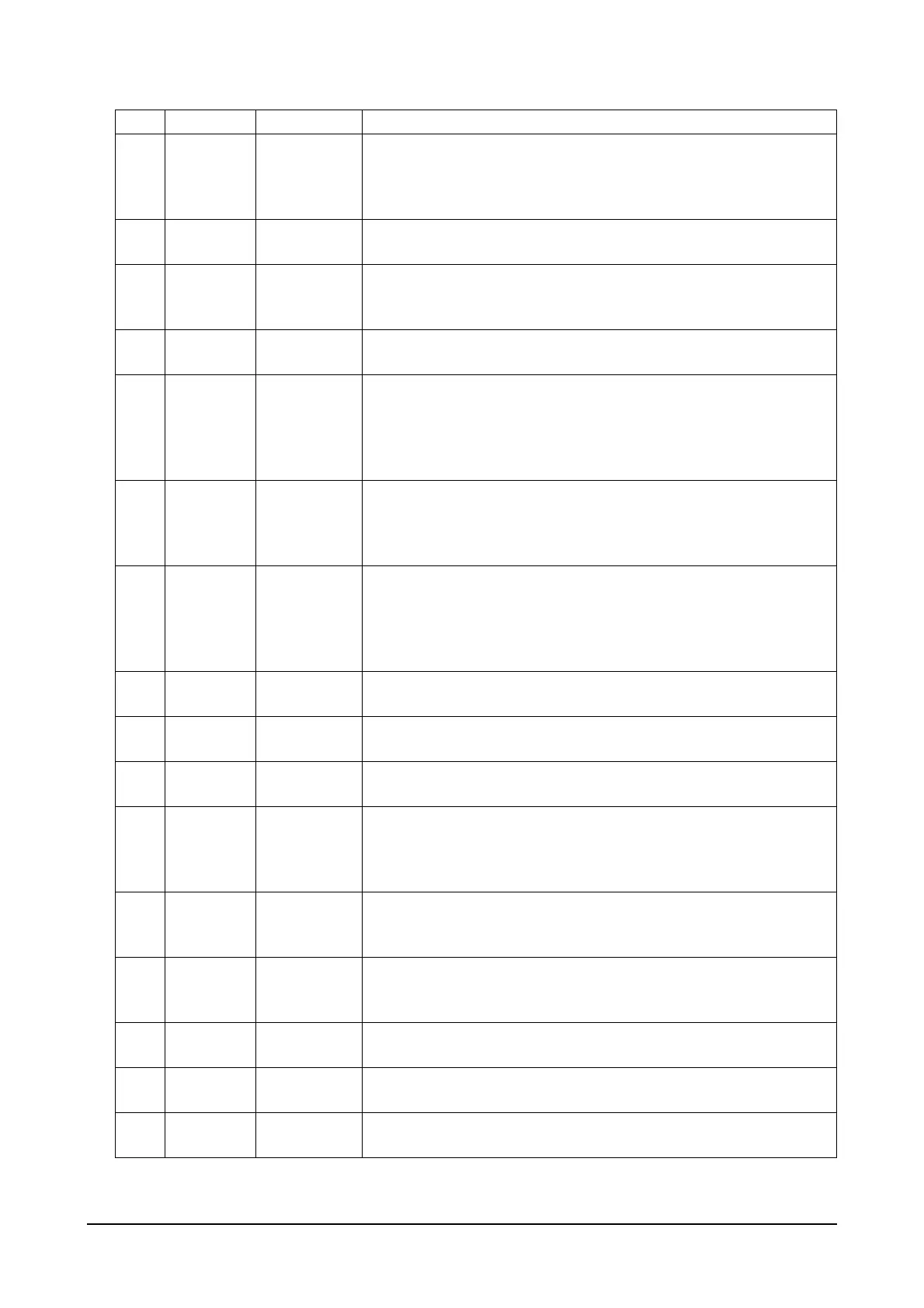
Droop
(K, L)
Input
Terminal K receives droop function selecting information.
Terminal L has a ground signal and the switch is connected to ter-
minals K and L. Once the terminal K is connected to the ground,
droop starts to operate.
8
Idle
(M)
Input
Terminal M receives idle function selection signals.
Once it is connected to the ground, idle operation starts.
9
AUX
(N)
Input
Terminal N receive load sharing and synchronization signal for par-
allel operation.
The signal level is an input between DC -5 and +5V.
10
10V
(P)
Output
Outputs are +10V/20 mA ratings and it can be used for various pur-
poses including power to external auxiliary devices.
11
Crank
Contact
Point
(1, 2, 3)
Output
The second crank contact point is a shared terminal while terminals
1 and 2 are for the contract point b and terminals 2 and 3 for the
contact point a. The contact point a starts to operate when the digi-
tal speed controller reaches at the RPM delivering control signals
to the actuator after the engine is activated.
12
Run Con-
tact Point
(4, 5, 6)
Output
The fifth run contact point is a shared terminal while terminals 4
and 5 are for the contact point b and terminals 5 and 6 for the con-
tact point a. The contact point a starts to operate when the engine
reaches its designated normal speed RPM.
13
Over
Speed
Contact
Point
(7, 8, 9)
Output
The eighth over speed contact point is a shared terminal while ter-
minals 7 and 8 are for the contact point b and terminals 8 and 9 for
the contact point a. The contact point a starts to operate when the
engine reaches its designated over speed RPM.
14
CAN
(10, 11)
I/O
Terminal 10 is for CAN-L communication and 11 is for CAN-H com-
munication. CAN-H and CAN-L are used for CAN communication.
15
Power
LED
Output
When DC+24 V power is supplied to the controller, the LED turns
on in red on the power level.
16
Pick-Up
LED
Output
When the controller receives normal input signals from the pick-up
sensor, the LED turns on in red on the pick-up level.
17
Crank
LED
Output
The 2- and 3-terminal contact point a starts to operate and the LED
turns on in red on the crank level when the digital speed controller
reaches at the RPM delivering control signals to the actuator after
the engine is activated.
18
Run
LED
Output
The LED turns on in red on the run level when the engine reaches
its designated normal speed RPM with 5- and 6-terminal contact
point a starting to operate.
19
Over
Speed
LED
Output
The LED turns on in red on the over speed level when the engine
reaches its designated over speed RPM with 8- and 9-terminal
contact point a starting to operate.
20
Error
LED
Output
The LED turns on in red on the error level when abnormal events of
the controller occur.
21 RS232 I/O
D-SUB 9PIN (male) is connected to the host through RS232 com-
munication port.
22 Ground Ground
The GND part and the ground should be earthed in shared connec-
tion.
No. Terminal I/O Type Terminal Functions
 Loading...