- 31 -
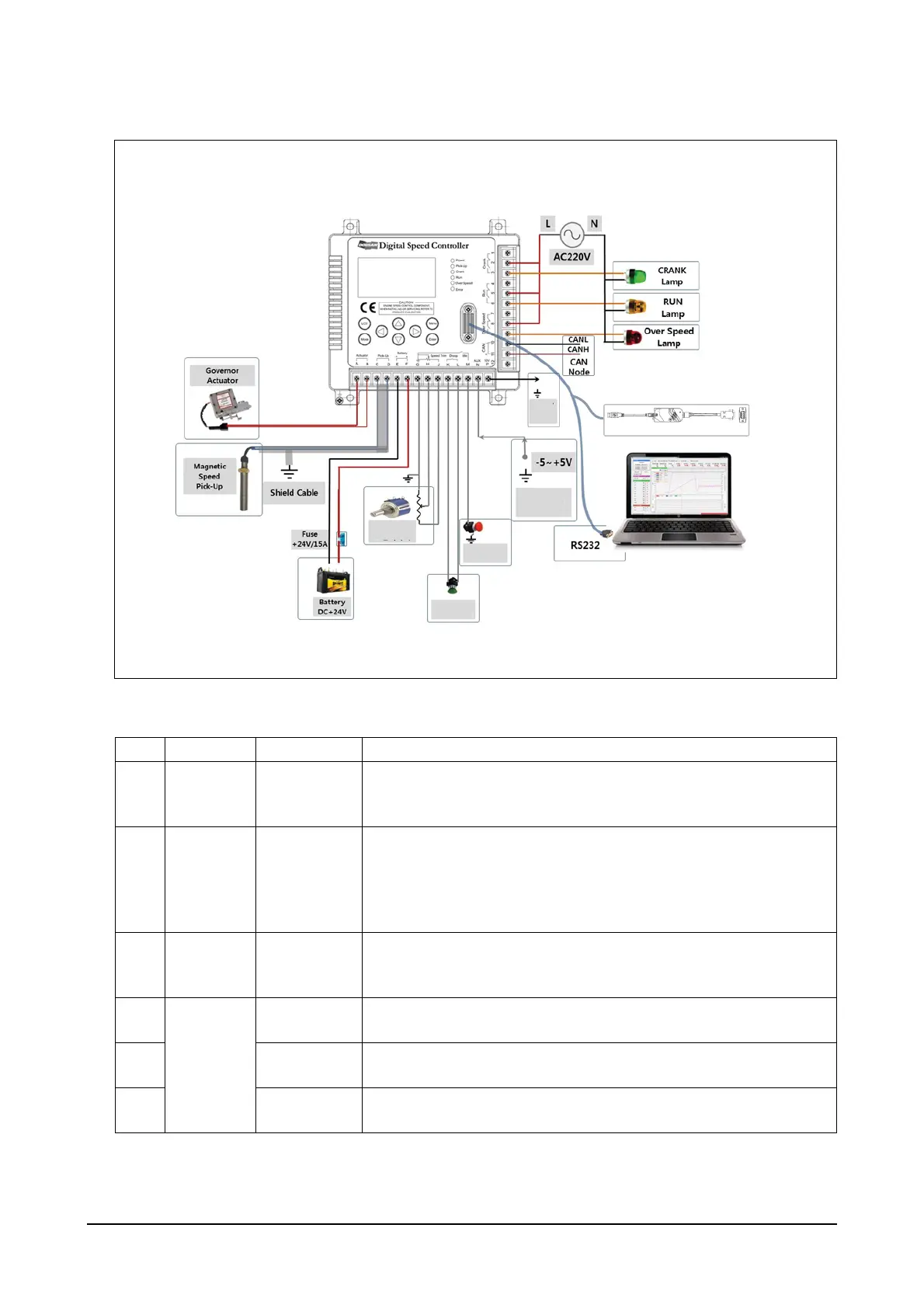
4. Product system diagram
5. Product I/O signals
EEX190001
Toolkit Cable
* CAN and R232 Communication Line
must to concect with shield Cable
* All of the GND(Earth) Mark
must to wiring to GND
System Configuration for Digital Speed Controller
Aux Input
Speed
Trim
+10V
Idle
Switch
Droop
Switch
No. Terminal I/O Type Terminal Functions
1
Actuator
(A, B)
Output
Outputs are actuator control signals.
Wiring should be 18AWG (105°C) or better. (However, terminals A
and B can be used regardless of their polarities)
2
Pick-Up
(C, D)
Input
Inputs are RPM sensor signals.
Terminal D should be connected to the ground in connection with
the shield cable. Gap between the RPM sensor and the gear tooth
should be adjusted between 0.9 and 1.1 mm (sensor inputs should
be at least 3V AC RMS).
3
Battery
Voltage
(-E, +F)
Input
It is a power input terminal for the controller and inputs are DC
+24V/15A. The positive pole of the battery should be connected to
the terminal F. (Back voltage protection circuit is built in.)
4
Speed
Trim
(G, H, J)
Input (G)
It has a ground signal and is connected to the ground of the poten-
tiometer.
5 Input (H)
Inputs are RPM trim signal values and the voltage level is between
0 and 5V. It is connected to the output of the potentiometer.
6 Input (J)
Outputs are DC +5V and it is connected to VCC of the potentiome-
ter.