OP001760
2-25
Operating Controls
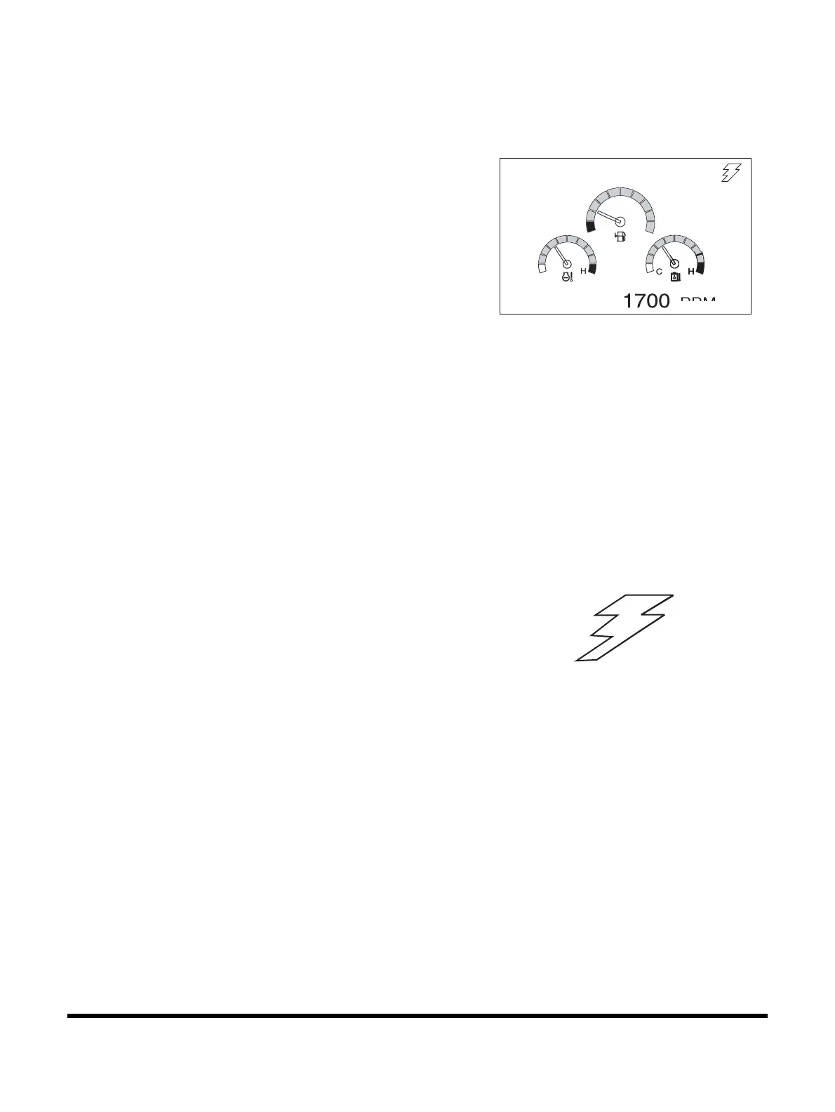
MULTIFUNCTION GAUGE AND
GRAPHIC INFORMATION
When the engine starter switch is turned to the "I" (ON) position, a
LOGO will appear on the display screen for about two seconds.
When the LOGO disappears, the multifunction gauge and
graphic information screen will appear.
The engine rpm is normally displayed at the bottom of the
screen when the starter switch is first turned "ON." Each time the
display selector button (19,
Figure 35) is pressed, the digital
readout changes in the following sequence; Engine speed
(RPM) -> Battery voltage (VOLT) -> Front pump pressure (BAR)
-> Rear pump pressure (BAR).
NOTE: See Figure 51 thru Figure 54.
A digital clock is located at the top of the display.
By using a combination of the mode selector buttons,
information for filters and oils can also be displayed.
The display can also be set for the desired language.
Refer to the “Setting Main Menu” on page 2-32 for the language
selection and information display sequences.
Communication Indicator
Indicates the condition of communication between main
controller and instrument panel.
1. Normal Condition:
The symbol will sequentially move like lightening.
NOTE: See Figure 51 thru Figure 54.
2. Abnormal Condition:
If the symbol is not displayed, it means there is a
communication error.
NOTE: See Figure 50.
Figure 48
02/05 [MO] 11:30
E
PEED
FG000043
FG000047
Figure 49
 Loading...