G-EMR
—
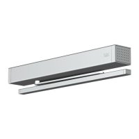
3DORMA
1a Installation on the pull side (hinge side)
2 Drill fixing points for closer and slide channel
using template TS 93 B or as per dimensioned
drawing. Drill holes of 12 mm dia. for 230 V AC power
supply (by others) and 8 mm dia. hole for connection
to any ceiling-mounted detectors and manual release
pushbuttons additionally required.
1b Installation on the push side (opposite hinge side)
2 A separate approval certificate is required in
conjunction with the fire/smoke check door concerned
(e.g. where DIN standards apply) – check local
regulations.
Drill fixing points for closer and slide channel using
template TS 93 G or as per dimensioned drawing.
Drill holes of 12 mm dia. for 230 V AC power supply
(by others) and 8 mm dia. hole for connection to
any ceiling-mounted detectors and manual release
pushbuttons additionally required.
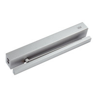
3a Install door closer and arm as specified in the fixing
instructions for the TS 93.
Connect the arm and slide shoe of the slide channel in
accordance with the TS 93 instructions, and adjust the
door closer.
3b Install door closer and arm as specified in the fixing
instructions for the TS 93.
Rotate slide channel 180°. Fit EMR unit as indicated.
Connect the arm and slide shoe of the slide channel
in accordance with the TS 93 instructions, and adjust
the door closer.
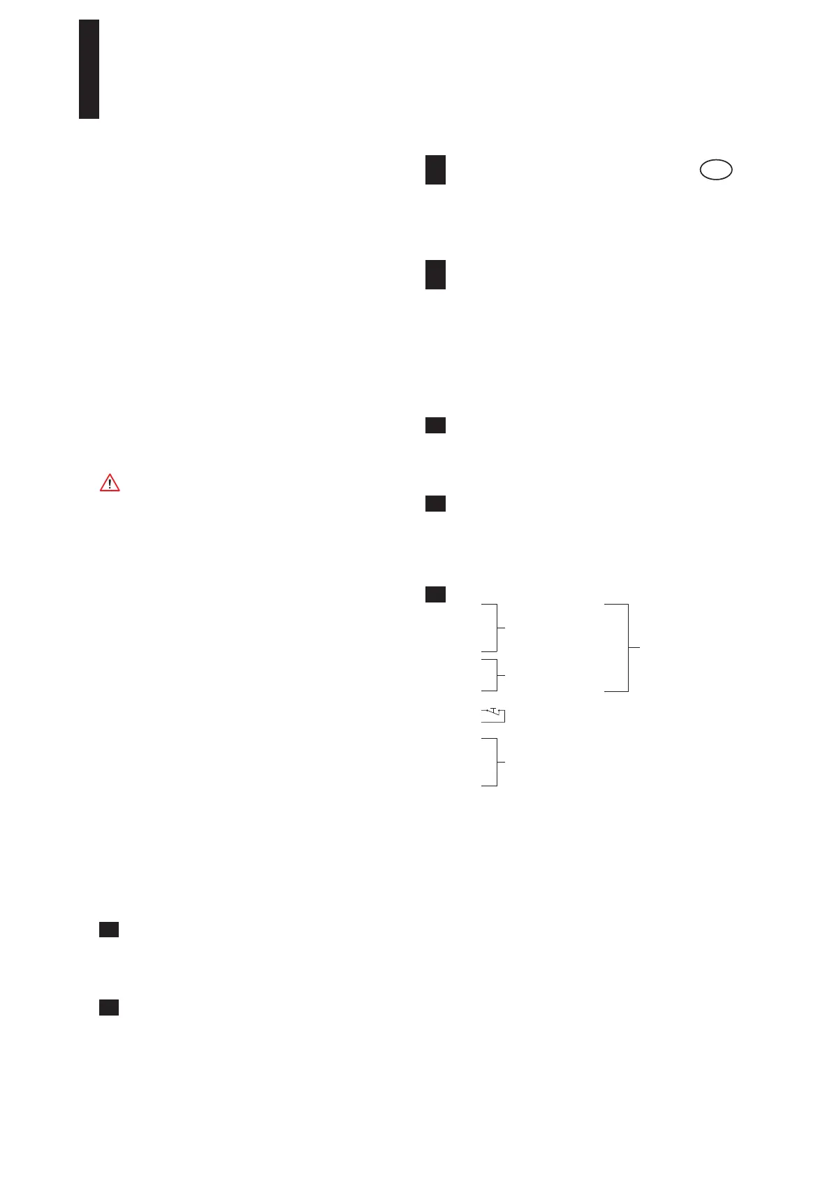
4 Terminal assignment EMR
Functions DIP switch
1 OFF = automatic reset
ON = manual reset
2 OFF = 1 radial operation (line)
ON = 2 radial operation (star)
3 OFF = without ceiling-mounted detector
ON = with ceiling-mounted detector
4 OFF = without manual push-button
ON = with manual push-button.
3
Connection of external
detectors with terminal
resistor
2)
Total output
rating max. 9.8 W
12
14
1 +
24 V DC output to
hold-open device(s)
4 –
2
External manual release
PB with terminal resistor
2)
10
7 NO
Floating change-over contact
SELV
24 V AC/DC, 2 A
8 NC
9 C
11 Floating terminal
16 Bus
2)
See connection diagrams
1)
AAuPZF of the Deutsches Institut für Bautechnik, Berlin
EN
Fixing Instructions
Technical Data EMR
Input: 230 V AC +10% / –15%
120 mA / 28 VA / 50 Hz
Output: 24 V DC / 460 mA / 11 W
Type of protection: IP 30
Protection class: II
Smoke switch: 24 V DC / 50 mA
Temperature: –20°C / +60°C
Rel. air humidity: max. 93% without condensation
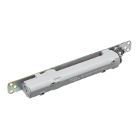
Technical Data EMF
Operating voltage: 24 V DC
Power input: 1,4 W
Rated for continuous
duty: 100% ED
Release torque: approx. 25 – 65 Nm at an opening
angle of 90° (dependent upon the
strength setting of the door closer).
Door opening angle: max. 120°
The unit is controlled by an external RMZ smoke detector.
Work on electrical equipment and systems may only be
performed by properly trained specialist personnel.
• Check to ensure that the line power supply (230 V AC)
has been disconnected and is no longer live.
• 10A/B miniature circuit breaker must be provided in
the supply circuit. This can also be used as the isolator
for disconnecting the RMZ and making it dead.
• The power cable leading to the EMR must be properly
secured to ensure effective strain relief.
• The power cable (NYM) conductor cross section should
not be greater than max. 1.5 mm
2
. The PE conductor
is not electrically utilised. The terminal (PE) should,
however, be used where a PE conductor is provided.
• Fire/smoke detectors controlling hold-open systems
must not be used to actuate any further alarm devices
(e.g. fire alarm transmission systems).
+
1)
• If the optional alarm module is installed, the cable
connecting it to the smoke switch must be led over and
across the measurement chamber in order to ensure
that smoke penetration is in no way hindered.
À Smoke detector
Á Electro-magnetic hold-open device
 RM smoke detector
à DORMA HT manual release pushbutton
for hold-open devices.
This pushbutton must not be concealed by the door
when in its hold-open position.
+
1)
a Installation arrangement of the EMR hold-open system
for applications where the bottom surface of the ceiling
is less than 1 m above the bottom edge of the lintel on
one or both sides of the door.
+
1)
See separate sheet for associated connection diagrams.
b If the bottom surface of the ceiling is more than 1 m
above the bottom edge of the lintel on one or both
sides of the door, two ceiling-mounted smoke detectors
must be installed in addition to the lintel-mounted
detector (EMR).
+
1)
See separate sheet for associated connection diagrams.
 Loading...