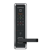
SVA 6xxx Commissioning instructions
060652-45532 – 05/2023 5
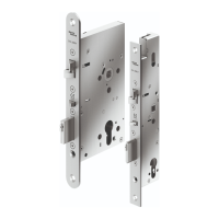
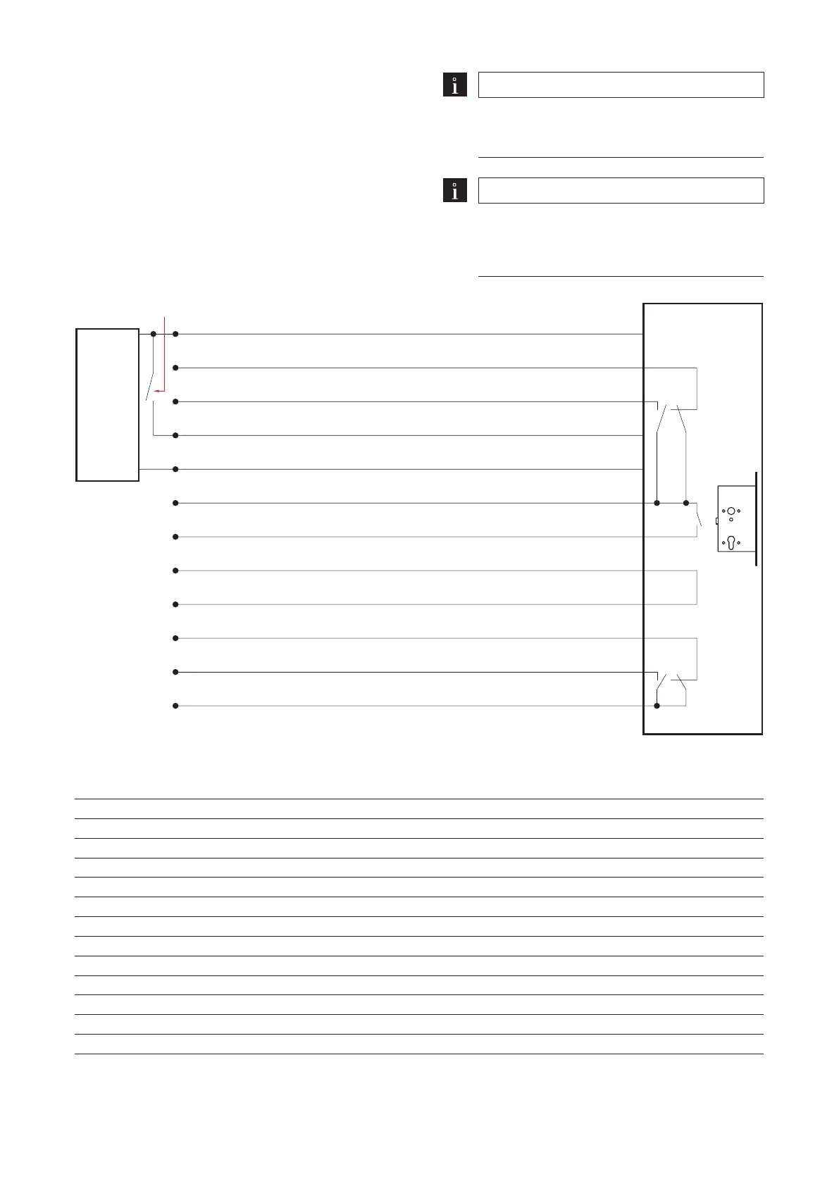
4 Pin assignment
4.1 Block diagram SVA 6xxx Stand Alone
Contact definition: Position of the switches when the
door is closed and locked. Door handle and cylinder
not actuated.
Note
For earthed door frames, the bridge on the
SVP-Ax100 connection cable’s plug must be
disconnected.
Note
Important with SVx 6000 for solid doors
The feedback contacts "SVx locked" and "Door
handle operated" only work if the lock is supplied
with voltage (GND - black and 12 V DC or 24 V DC -
white).
Operating current = NO / Quiescent current = NC
Black GND
Brown "Trip latch on", NC
Pink/gray "SVP/SVZ/SVA unlocked", NO
Engage the door handle via GND contact /
Red Operating current = NO / Quiescent current = NC
White 12 or 24VDC (stabilized)
"SVP/SVZ/SVA unlocked" and "Trip latch on"
Yellow and cylinder contact, C
Green Cylinder contact, NO
Gray Anti-tamper circuit
Pink Anti-tamper circuit
Red/blue "SVP/SVZ/SVA locked", NC
Blue “Door handle operated”, NO
Violet "SVP/SVZ/SVA locked" and "Door handle operated", C
SVP/SVZ/
SVA6xxx
function
Stand-alone
Stabilized 24
VDC power
supply
4.2 Connecting cable SVP-A 1100/2100
Cable color Connection / function
Black GND
Red not in use
White +24VDC
Brown not in use
Violet Locked, output switches to GND, 30mA at max. 30VDC
Red-blue not in use
Blue not in use
Green not in use
Gray-pink Bolt contact*
2
Yellow Bolt contact*
2
Gray RS485 N*
Pink RS485 P*
*
1
only in combination with SVA2xxx(F) with SVI2xxxF
*
2
Optional
 Loading...