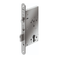
4.5.2 Mount wide style door lock
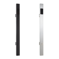
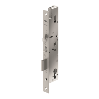
1. If necessary, change operating mode fail secure
(AS) to fail safe (RS)(Fig. 21).
Fig. 21
AS
RS
1.
2.
3.
Change fail secure to fail safe operating current
2. Connect the cable (Fig. 22).
TIPS AND RECOMMENDATIONS
If a lock is being replaced, a cable with a
severed bridge can still be used.
Fig. 22
SVP-A 1100/2100
SVP 2000
SVP 2000F
SVP 4000
SVP 6000
SVZ 6000
SVP 5000
Connect cable
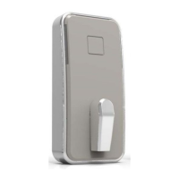
3. Insert the door lock into the door leaf cut-out (Fig.
23).
Fig. 23
Compressed air
air comprimé
Druckluft
Insert door lock
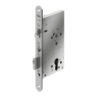
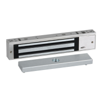
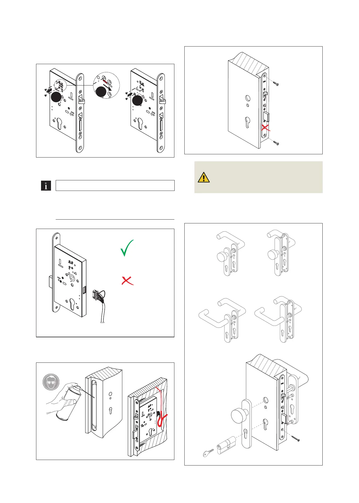
4. Screw the door lock tight (Fig. 24).
Fig. 24 Screw door lock tight
5.
Attention!
Risk of property damage due to the use
of an incorrect cylinder screw with the
locks SVP 2000 and SVP 2000F.
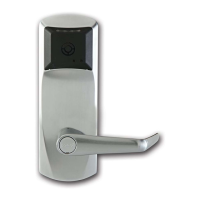
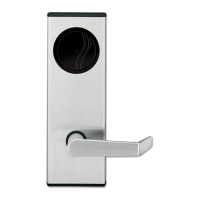
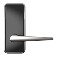
Mount the door handle and locking cylinder (Fig.
25). For SVP 2000/2000F locks, use only the
screw supplied with the lock to secure the cylinder
(DIN EN ISO 7046-1, M5 x (backset + 5 mm)).
Fig. 25 Mount door handle and locking cylinder
13
SVP/SVZ door locks 2020-03WN 059744 45532
dormakaba Mounting instructions Mounting