EasyManua.ls Logo

Dormakaba SVP User Manual

Dormakaba SVP
20 pages
To Next Page IconTo Next Page
Page #1 background imageLoading...
Page #1 background image
SVP/SVZ door locks
Mounting instructions
WN 059744 45532/14767
2020-03
EN
Contents
1 About this document 1
2 Safety 2
3 Product description 3
4 Mounting 8
5 Parameterization (SVP2000/2000F only) 15
6 Integrated Power Reserve module test
(SVP2000F) 18
7 Pin assignment 18
8 Complete mounting 19
9 Error messages 20
10 Maintenance 20
11 Disassembly and disposal 20
1 About this document
1.1 Contents and purpose
SVP/SVZ door locks are available in various designs
for tubular frame doors and for solid doors. This
manual describes mounting in tubular frame and solid
doors.
1.2 Target group
SVP/SVZ door locks must only be mounted by
technically qualified personnel.
1.3 Other applicable documents
Manual for the connection cable SVP-A1100/2100
(not necessary for SVP5000)
Mounting instructions for the components used, e.g.
the door handle
1.4 Abbreviations
SVP
Emergency lock with self locking
action
SVZ
Access control lock with
self locking action, without
emergency escape action
2000, 2000F,
4000, 5000,
6000
All versions of a door lock; the
exact lock type is marked with 3
digits instead of zeros.
TMS Soft®
Software for the dormakaba
door management system (TMS)
DCW® bus
DCW® is the short form for
"DORMA Connect & Work".
A dormakaba-owned fieldbus
system for the connection of up
to 4identical components to a
DCW® central unit.
CAN bus
Serial fieldbus system according
to ISO11898-3, for connecting
several components to one cable
harness
RR Tubular frame locks
VB Solid door locks
1.5 Symbols used
1.5.1 Hazard categories
WARNING
This signal word indicates a possible
hazardous situation which may result in
death or serious injury if not averted.
ATTENTION
This signal word indicates a situation of
potential risk, which could lead to damage
to property or the environment if not
averted.
TIPS AND RECOMMENDATIONS
This signal word indicates useful information
for efficient and trouble-free operation.
1.5.2 More symbols
1. 2.
Sequence of action steps
1
2
Item numbers used in image
caption
Question and Answer IconNeed help?

Do you have a question about the Dormakaba SVP and is the answer not in the manual?

Dormakaba SVP Specifications

General IconGeneral
Operating Temperature-20°C to +60°C
MaterialStainless Steel
Emergency Exit FunctionYes
BacksetVaries by model
StandardsEN
Power Supply24 V DC
Voltage24 V DC
Current ConsumptionVaries by model
Holding ForceVaries by model
Door ThicknessVaries by model
WeightVaries by model
FinishStainless Steel
Fail-Safe/Fail-SecureFail-secure (power-to-release)

Summary

About this document

Contents and Purpose

Explains the manual's scope for SVP/SVZ door locks in different door types.

Target Group

Specifies that SVP/SVZ door locks must be mounted by technically qualified personnel.

Other Applicable Documents

Lists related documents like connection cable manuals and mounting instructions.

Abbreviations

Lists abbreviations used in the manual, such as SVP and SVZ.

Symbols Used

Hazard Categories

Explains hazard symbols like WARNING and ATTENTION with their meanings.

More Symbols

Details symbols for sequence of action steps and item numbers in captions.

Product Description

Basic Functions

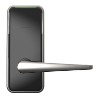
Explains automatic locking, two-point locking, and emergency unlocking features of SVP/SVZ locks.

Installation Situation

Illustrates the typical installation setup of the door lock and associated components.

Technical Information

Provides technical specifications like temperature, humidity, protection category, and dimensions.

Variants

Details different SVP/SVZ lock types (5000, 4000, 6000, SVZ 6000, 2000, 2000F) and their features.

Classification: Tubular Frame Locks

Lists classifications and certifications for tubular frame SVP/SVZ door locks.

Classification: Solid Door Locks

Lists classifications and certifications for solid door SVP/SVZ door locks.

Tubular Frame Locks: Parts Included

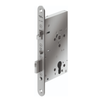
Shows the components provided for tubular frame locks: door lock, striking plate, and screws.

Tubular Frame Locks: Lock Dimensions

Displays detailed technical drawings and dimensions for tubular frame locks.

Solid Door Locks: Parts Included

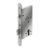
Lists the parts included for solid door locks, including cylinder fixing screws.

Solid Door Locks: Lock Dimensions

Provides technical drawings and dimensions specific to solid door locks.

Solid Door Locks: Door Versions

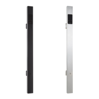
Illustrates different door versions (Rebated, Flush) for solid door locks.

Mounting

Safety During Mounting

Warns about risks like door deformation and emphasizes proper installation safety.

Requirements for Mounting

Outlines conditions for mounting, like door specifications and escape route considerations.

Tools and Auxiliary Materials

Lists necessary tools and materials for the mounting process, including cylinders and handles.

Preparatory Work for Tubular Frame Locks

Details the precise mill-cutting and drilling required for tubular frame locks.

Preparatory Work for Solid Door Locks

Explains the mill-cutting and drilling procedures for solid door locks.

Mounting Tubular Frame Locks

Step-by-step guide for mounting tubular frame locks, including cable connection and securing.

Mounting Wide Style Door Locks

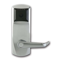
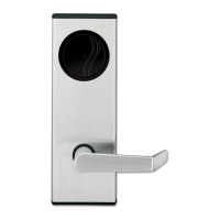
Instructions for mounting wide style door locks, including fail-safe/fail-secure mode and cylinder screw.

Parameterization (SVP 2000/2000F)

LED Display Overview

Explains the LED signals indicating status, operation mode, and error messages.

Operation Mode Settings

Details how to set the operation mode (DCW, CAN, Stand Alone) via LED signals.

Bus Address Configuration

Describes how to assign unique addresses to SVP door locks for bus operation.

End Resistor Settings

Explains the function and setting of the terminating resistor for CAN bus operation.

Default Settings

Lists the default parameters for operation mode, bus address, and terminating resistor.

System Start LED Display

Shows how the LED indicates parameters at system start-up for different modes.

Parameter Change Requirements

Outlines conditions for changing parameters, like power and system start time.

Parameterization Flow Chart and Methods

Illustrates the parameter setting process using symbols and flow charts for various modes.

Setting for DCW® Bus Operation

Step-by-step guide to configure the lock for DCW® bus communication and address assignment.

Setting for CAN Bus Operation

Instructions for configuring the lock for CAN bus, including address and resistor settings.

Setting for Stand Alone Operation

Procedure to set the lock for Stand Alone mode, including LED indications.

Navigating Parameter Selections

Describes how to jump between different parameter settings or go back in the process.

Canceling Parameterization

Explains how parameter changes are saved or aborted and what happens on power interruption.

Integrated Power Reserve Module Test

Test Procedure and Error Indication

Details the internal Power Reserve module test schedule and error reporting for SVP 2000F.

Pin Assignment

SVP 2000(F) Cable Pinout

Provides a detailed table of pin assignments for SVP-A 1100/2100 cables in different operation modes.

Smoke Detector Wiring

Illustrates the wiring diagram for connecting smoke detectors with SVP 2000/SVP 2000F.

Complete Mounting

Mounting Procedure Overview

Covers measuring distances, checking parts, ensuring locking points are clear, and force measurements.

Error Messages

LED Display Error Codes

Lists LED error patterns, their causes (power, test failure, connection), and recommended actions.

Maintenance

Monthly Maintenance Steps

Outlines monthly checks for safe operation, including checking parts, locking points, and actuating forces.

Disassembly and Disposal

Product Disposal Guidelines

Instructs on safe disassembly and environmentally friendly disposal of the product, avoiding domestic waste.

Related product manuals