XMPI0MTIRPD2ST021 7/24 Ed. 2021
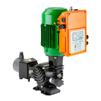
2. ELECTRICAL INSTALLATION OF THE INVERTER MOTOR IN THE SYSTEM
It is essential to read this chapter before proceeding with the electrical installation of the new or
replacement inverter or with re-installation following maintenance in the existing system.
Installation of the motor-inverter in the system may only be carried out by electrical installers,
manufacturers and professional operators in possession of the technical and professional
qualifications required by the laws in force. Installation is not permitted for private individuals or end
users.
With the exception of action with appropriate tools (3 mm blade screwdriver) on the connection
terminals (when the inverter is powered down), no operation is required or permitted on any part
of the inverter. In particular, it is not permitted to separate the electronic board from the base and
it is not permitted to tamper with, modify, replace or eliminate any of the electronic components
mounted on the inverter, failure to do so will invalidate the warranty.
After completing the wiring operations described in this chapter and before switching on the power
supply, it is essential to close the cover of the inverter to ensure the electrical safety of the
installation.
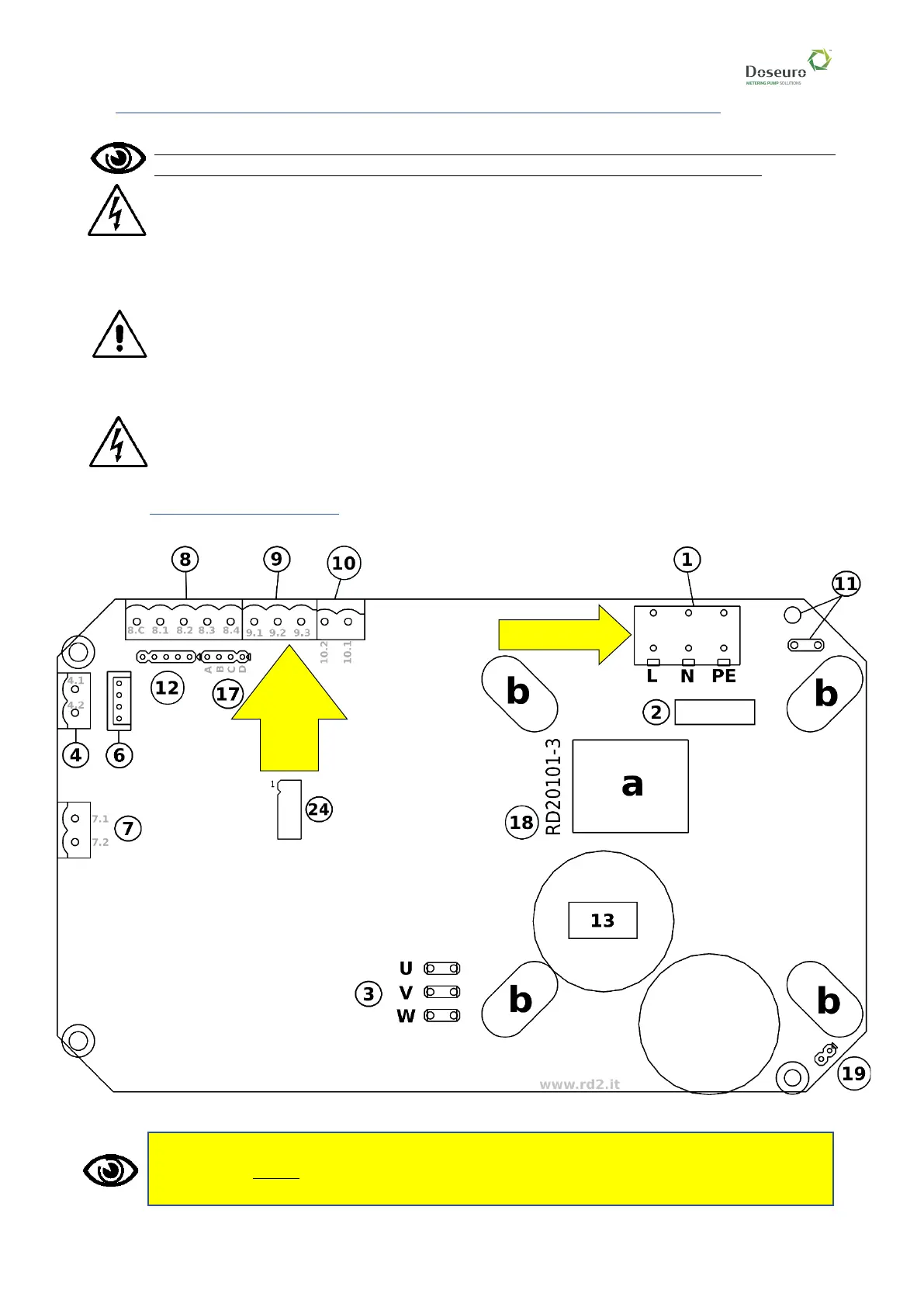
2.1. CONNECTION DIAGRAMS
Layout of the inverter board
Pay particular attention to the power supply: in standard configuration it is 230V/1ph. 50-60 Hz
but may be a special product [par. 1.1], in which case refer to the correct feeding in the
technical specification.