EasyManua.ls Logo

Doseuro Rapida 2.0 - Inverter Motor Power Supply; Details of the Control Terminal Section

Doseuro Rapida 2.0
24 pages
Print Icon
To Next Page IconTo Next Page
To Previous Page IconTo Previous Page
Loading...
XMPI0MTIRPD2ST021 8/24 Ed. 2021
Figure 2
Key:
1
Power supply terminal block
10
HSI/Encoder control input connector
2
Power fuse
11
Earth connection faston
3
Motor connection faston
12
Input connector reserved for 4-key keyboard
4
RS485 serial connection terminal
13
Inverter registration label
6
ALS-1 terminal connector and RS485 serial connector
17
Analog input mode selector (Volt/mA)
7
Programmable output connector
18
Hardware version reference
8
Control input connector
19
Filter stage closure jumper on PE
9
Potentiometer/analogue reference connector
24
Pin Header 5x2 Display
2.2. INVERTER MOTOR POWER SUPPLY
The power cable must be fed into the inverter through the PG11 cable gland on the side of the inverter box.
Use 2-pole sheathed cable plus earth, of suitable cross-section.
Shielding of the power cable is not required. However, for reasons of electrical safety and EMC protection,
correct earthing is absolutely essential. For this purpose, the PE terminal must be connected to the protective
conductor in the power supply cabinet.
For the power supply, the inverter is equipped with a spring-loaded terminal block (1) which guarantees
maximum mechanical tightness of the connection. The cable must have a circular cross-section and a diameter
suitable for the cable gland.
Press the orange terminals perpendicularly to the surface of the printed circuit board with a screwdriver with
a 2.5÷3 mm blade and insert the stripped wire for about 5 mm until resistance is encountered, then release
the terminal and check, with a slight pull on the wire, the tightness of the connection.
The protection fuse (2) is type 5x20 mm / 250 V - T10A (0.75 kW).
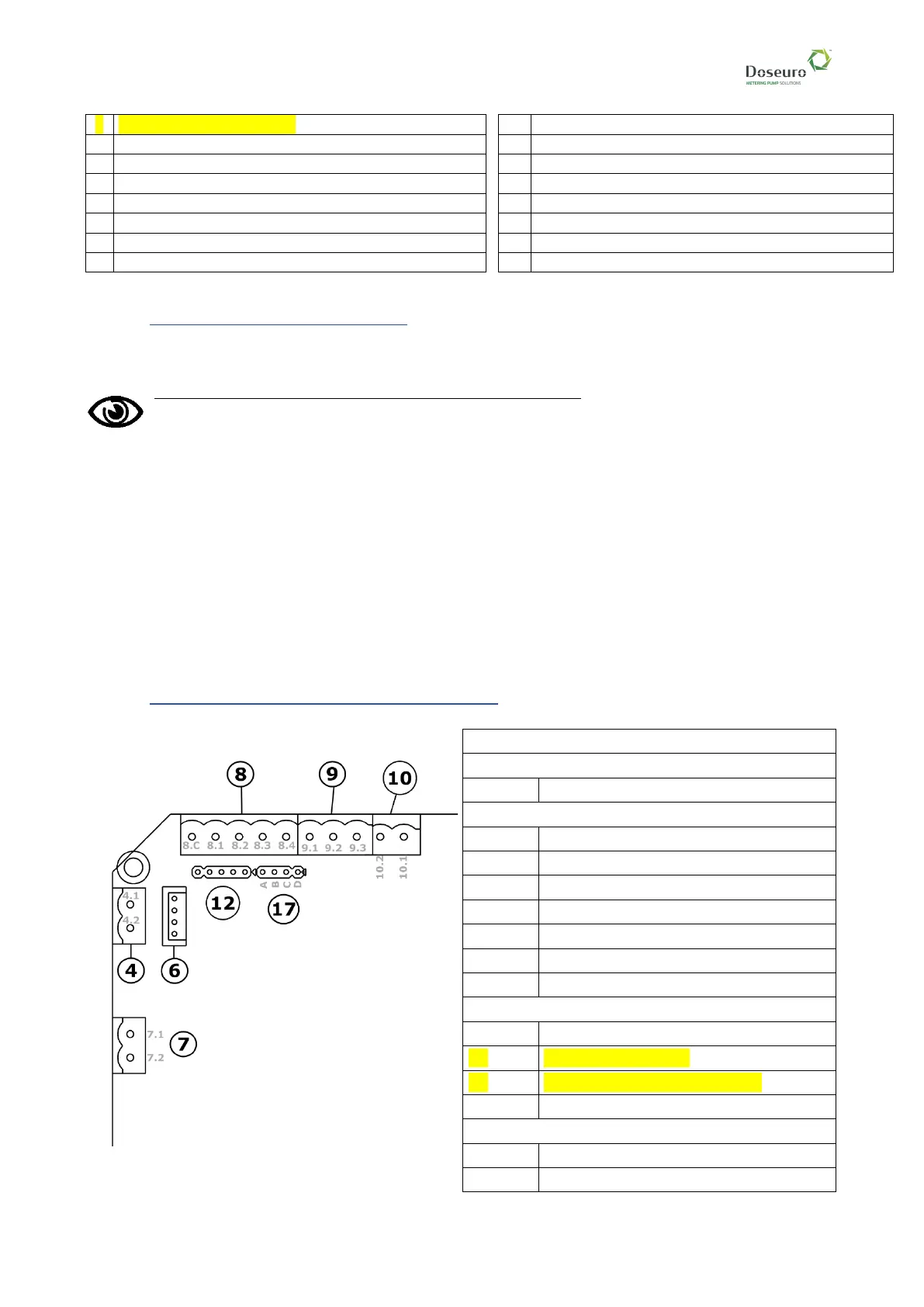
2.3. DETAILS OF THE CONTROL TERMINAL SECTION
FUNCTION OF TERMINALS
Digital outputs:
7.1 - 7.2
ALS-1 PROGRAMMABLE RELAY OUTPUT
Digital inputs:
8.1
ENTRANCE 1
8.2
ENTRANCE 2
8.3
ENTRANCE 3
8.4
ENTRANCE 4
8.C
MUNICIPALITY ENTRANCES
10.1
HSI INPUT 1/INPUT ENCODER A
10.2
HSI 2 INPUT/INPUT ENCODER B
Analogue speed reference:
17
ANALOGUE INPUT MODE SELECTION.
9.1
GND ANALOGUE INPUT
9.2
PROPORTIONAL SPEED REFERENCE
9.3
+10V
RS485 connection:
4.1
RB-
4.2
RA+