Do you have a question about the DOTECH CX9230 Series and is the answer not in the manual?
Overview of the controller's advanced PID control, auto-tuning, and sensor input capabilities.
Lists the types of chillers and temperature control systems compatible with the controller.
Details and diagrams of the controller unit, sensors, and power transformer.
Instructions for physically installing the controller unit and connecting components.
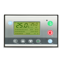
Illustrates the physical front panel and button layout of the CX9230 controller.
Explains the various elements displayed on the controller's screen, including status and values.
Details the purpose and usage of each button on the controller interface.
Lists all possible trip alarms, their codes, and the corresponding remarks or causes.
Details system status messages like power on, parameter change, and machine start/stop.
Provides general information, default values, and access levels for various parameters.
Defines daily operational schedules for the controller, including start and stop times.
Explains the system's logging mechanism for recording events and their occurrences.
Lists parameters related to scheduled maintenance tasks and checks.
Details specific parameters that trigger trip conditions and alarms.
Lists and explains parameters for low temperature alarms and their settings.
Details parameters for high and low temperature alarms, including delay and reset settings.
Explains parameters for low and high-pressure alarms, including delay and reset configurations.
Details configuration options for digital inputs and outputs, including alarm and status assignments.
Explains different output modes for Y1 and Y2, such as heating, cooling, and condenser fan control.
Defines the types of output signals, including analog (4-20mA) and SSR.
Parameters related to compressor installation, run delay, and pump-down operations.
Configuration for control sources, sensor ratios, and power return.
Details parameters for PID control, including auto-tuning, gains, and time constants.
Settings for pressure sensors, including limits, offsets, and types.
Settings for language, access codes, communication ID, and alarm buzzer.
Parameters for factory tests, input calibration, and filter adjustments.
Details transmission line, baud rate, parity, and protocol type for Modbus RTU.
Lists the status of digital input ports and their corresponding signal states.
Lists the status of digital output ports and their corresponding signal states.
Details the states of trip conditions, alarms, and sensor checks.
Lists data points like current temperature and pressure with their ranges and scaling.
| Brand | DOTECH |
|---|---|
| Model | CX9230 Series |
| Category | Controller |
| Language | English |