60
Electrical System
accessories and electronics at low speed when
the charging system output from the engines is
minimal. Refer to the engine owner’s manual for
additional information on the battery requirements
for your engines.
There are three remotely activated battery switch-
es and one remotely activated emergency parallel
switch located in the systems compartment. The
remote battery switches and emergency parallel
switch are activated by special switches in the
helm switch panel. Each battery switch has a
manual override that can activate (enable) or de-
activate (disable) the switch if the remote switch
or relay fails. The manual override is a yellow
knob on each battery switch that can be pressed
to manually activate the switch or rotated to reac-
tivate remote activation of the switch or to lockout
the switch in the OFF position when servicing the
electrical system. The normal operating position
for each switch is the “Enabled” Position. Refer
to the instructions printed on each switch and/or
the battery switch operating manual for additional
information on the remotely activated switches.
Single Engine Battery Systems
Single engine boats have provision for three bat-
teries located in the aft systems compartment
below the bench seat. One for the engine and
two in parallel for the house and electronics cir-
cuits. These batteries should be of the size and
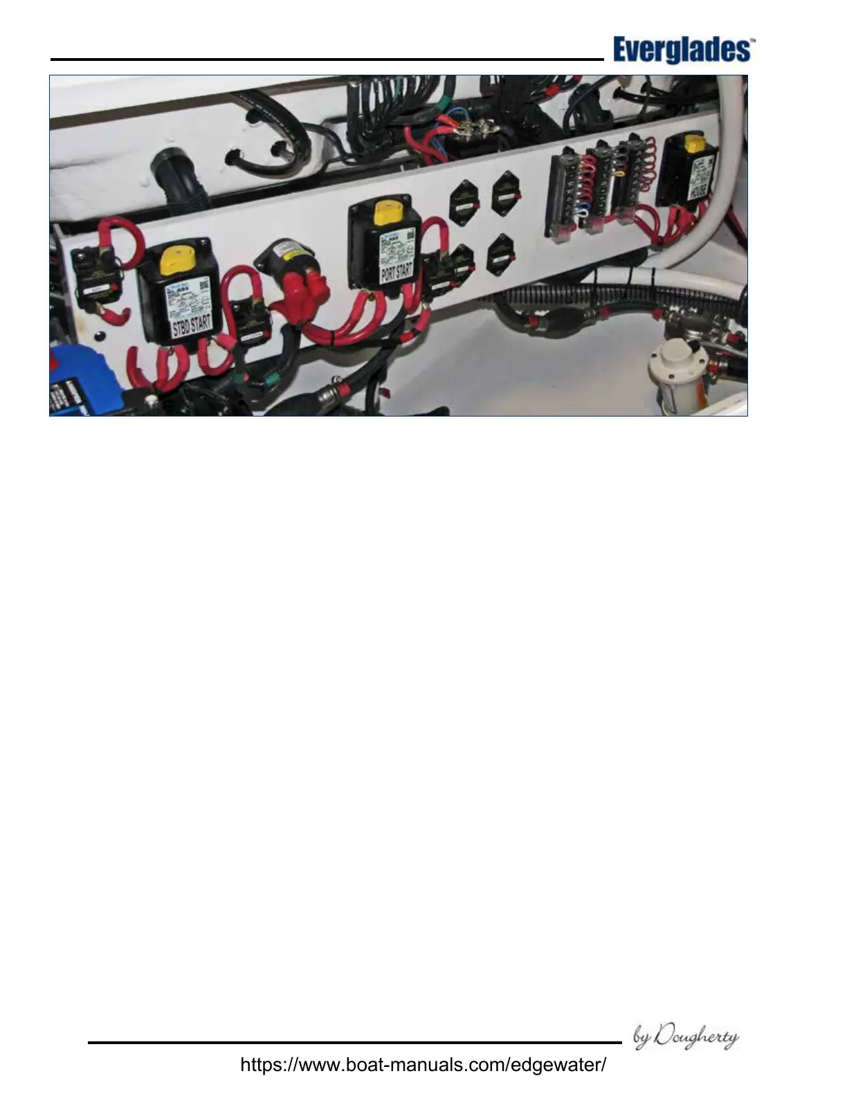
Battery Switches, Fuse Panels & Main Circuit Breakers - Twin Engine Models
capacity recommended by the manufacturer of
your engines. These specications should be con-
sidered to be the minimum size battery required.
Consider increasing the capacity of the batteries if
you will be trolling, drift shing or have extensive
electronics on board. Larger batteries will give
you additional capacity to operate the baitwell,
DC accessories and electronics at low speed when
the charging system output from the engines is
minimal. Refer to the engine owner’s manual for
additional information on the battery requirements
for your engines.
There are three remotely activated battery switch-
es and one remotely activated emergency parallel
switch located in the systems compartment. The
remote battery switches and emergency parallel
switch are activated by special switches in the
helm switch panel. Each battery switch has a
manual override that can activate (enable) or de-
activate (disable) the switch if the remote switch
or relay fails. The manual override is a yellow
knob on each battery switch that can be pressed
to manually activate the switch or rotated to reac-
tivate remote activation of the switch or to lockout
the switch in the OFF position when servicing the
electrical system. The normal operating position
for each switch is the “Enabled” Position. Refer
to the instructions printed on each switch and/or
the battery switch operating manual for additional
information on the remotely activated switches.
https://www.boat-manuals.com/edgewater/
 Loading...