61
Electrical System
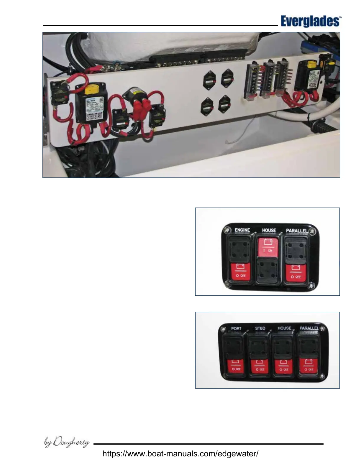
Remote Battery Switch Operation
Each battery switch and the emergency parallel
switch is controlled by a switch in the helm battery
switch panel. Slide the label down and press the
top of the remote switch to engage the battery
switch. A red light will illuminate to indicate that
the battery is now ON. To turn o, simply slide the
label up and press the bottom of the momentary
switch. The red light may not turn o immediately
or will slowly fade out if there are no loads present
on the system. This is normal as the capacitors
in the system drain.
Automatic voltage sensitive relays (VSR) control
the charging of the engine and house batteries
whenever an engine is operating. The house and
engine batteries can be temporarily connected in
parallel by the emergency parallel switch to pro-
vide additional starting current for each engine.
The engine and house batteries are also charged
by the battery charger whenever it is operating.
The VSR battery isolator systems manage the
charging current for the 12 volt system whenever
the engines are running. The systems automati-
cally sense the condition of each battery and direct
the available current to the batteries that require
charging. When one or both engines is started,
the engine alternator(s) start to recharge the
batteries. This charging current passes through
Battery Switches, Fuse Panels & Main Circuit Breakers - Single Engine Models
Twin Engine Remote Battery Switches
Single Engine Remote Battery Switches
https://www.boat-manuals.com/edgewater/


 To Next Page