CONTACT US AT www.DRpower.com 15
Always make sure you remove the screwdriver from the head assembly when
finished. Failure to remove the screwdriver could cause injury when the head
assembly is engaged.
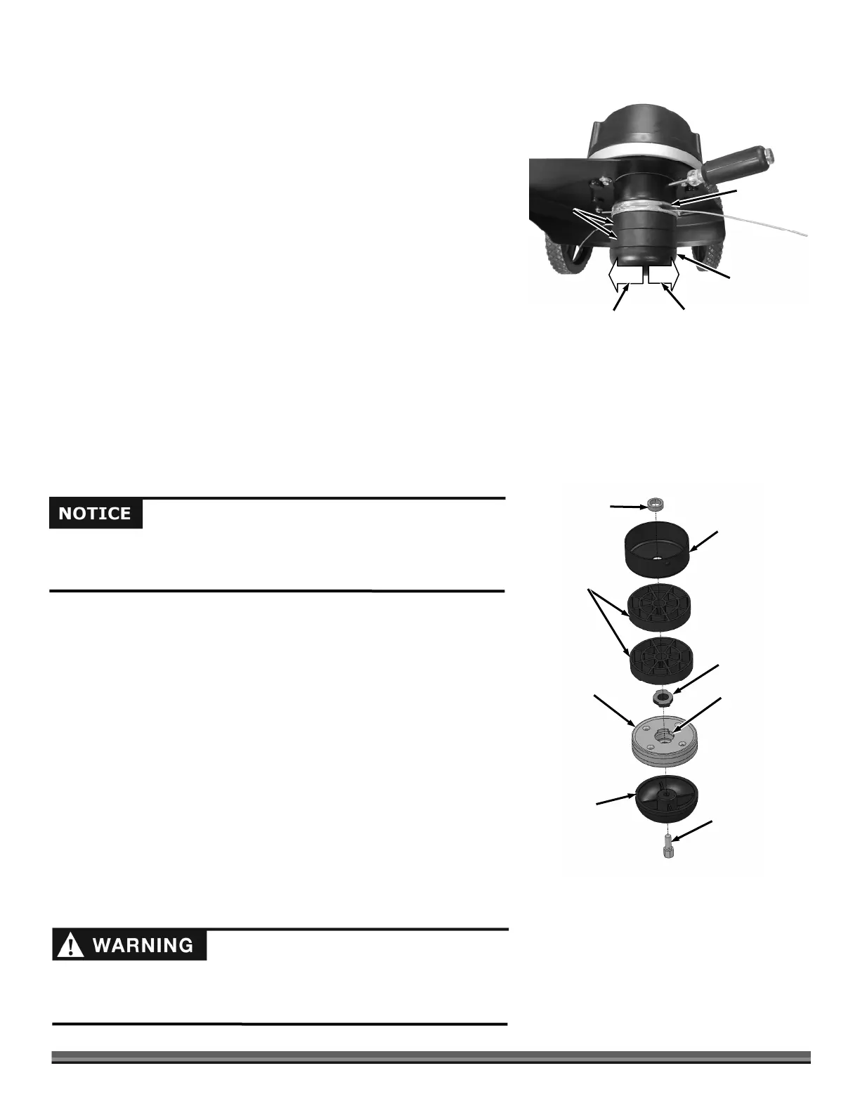
Tighten
Loosen
Quick Lock
Figure 13
Mow-Ball
®
Molded
Spacers
Replacing the Mow-Ball
®
or Quick-Lock™ parts
Tools and Supplies Needed:
Phillips head Screwdriver with at least a 6" shank
Gloves
Disassembly
1. Align the hole in the Anti Wrap Canister with the hole in the internal housing
at the location shown (Figure 13).
2. Insert a Philips Head Screwdriver into the hole in the Anti Wrap Canister
and the hole in the internal Housing.
3. Rotate the Mow-Ball
®
Assembly until the Screw Driver slides into a hole in
the shaft, locking it into place.
4. Looking up at the bottom of the Mow-Ball
®
, turn it clockwise until it
unscrews completely from the Bearing Housing.
Note: If the Mow-Ball
®
continues to turn, but does not come off, check to be sure that you locked the Screwdriver into the shaft.
If the Mow-Ball
®
will not turn by hand a 9/16" Socket can be used on the Bolt (inside the bottom of the Mow-Ball) to loosen it.
You may need to clean grass or debris out of the recess first.
5. Slide the Quick-Lock, Spacers, Anti Wrap Canister, and Spacer off the Shaft (Figure 14).
Assembly
1. Place the Spacer and Anti Wrap Canister (with the lip facing up) onto the
Shaft (Figure 14).
2. Install the Molded Spacers, Quick Lock with Adapter hole and Adapter on
top of Quick Lock onto the Shaft.
Note: Refer to the “Head Height Adjustment” section for adjusting the Trimmer
Head cutting heights.
3. Place the Mow-Ball
®
Bolt into the hex cavity of the Mow-Ball
®
so it is going
up through the top of the Mow-Ball
®
.
4. Looking up from the bottom of the Mow Ball
®
, hold the Bolt Head in place
with your finger and turn the Mow-Ball
®
clockwise to start the Bolt into the
Shaft (Figure 13).
5. Tighten the assembly securely by turning the Mow-Ball
®
clockwise until
hand tight.
6. Remove the Screwdriver.
Note: When finished, there should be no gaps between any of the components.
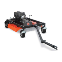
Mow-Ball
®
Figure 14
Mo
-Bal
®
Bolt
Quick Lock
dapte
Molded Spacers
nti-Wrap Can
Spacer
dapter Hole
(facing up)
Improper installation can cause damage to the trimmer bearings. Follow
these directions carefully to protect your machine from damage. Reassemble
the components in the order shown for lowest cutting height (Figure 14).