CONTACT US AT www.DRpower.com 25
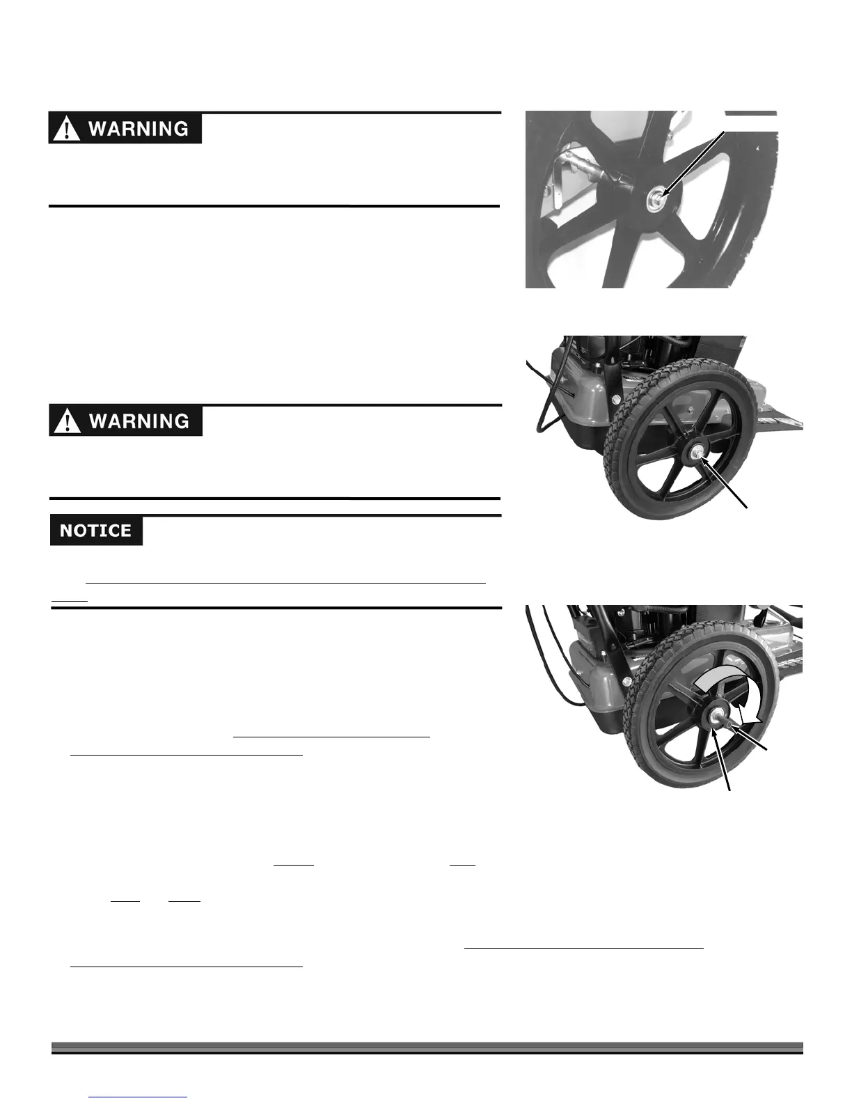
Figure 42
Red Mark on Outside of Hub
(For Right Side Wheel)
Plastic
Insert
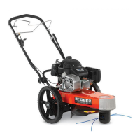
Wheels - SPRINT and PRO
Tool needed:
5/8" Wrench
1. Block and stabilize the machine so that the Wheels are off the ground.
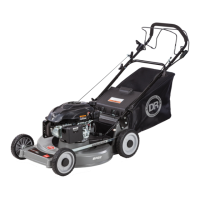
2. Loosen and remove the Locknut (Figure 40).
3. Slide the Wheel off the Axle.
4. Reverse the steps to install the Wheel.
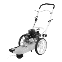
Wheels - PRO-XL SELF-PROPELLED
Tool needed:
5/8" Wrench
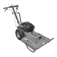
1. Block and stabilize the machine so that the Wheels are off the ground.
2. Loosen and remove the Locknut (Figure 41).
3. Turn the Wheel off the Axle, clockwise for the Right side Wheel
and
counterclockwise for the Left side Wheel
.
NOTE: Left and Right are determined from the Operator’s position.
4. Inspect the new Wheel Hub for markings (Figure 42). One Wheel will have a
RED Label on the outside and one Wheel will have a BLUE Label on the
outside.
5. If you are installing a Wheel on the RIGHT
side of the Mower, the RED Label
should face the outside away from the Mower. If you are installing a Wheel
on the LEFT
, the BLUE Label should face away from the Mower.
6. Orient the Wheel so that the correct color Label faces away from the body of the Mower.
7. Place the Wheel on the Axle and slowly turn the Wheel onto the Axle (again, clockwise for the Right side Wheel
and
counterclockwise for the Left side Wheel
.
NOTE: The new Wheel will have a red Sleeve inside the Hub. This Sleeve keeps the Wheel Splines in place during shipment. As the
Wheel moves onto the Axle, the Sleeve will push out of the Wheel Hub. You can then remove and store the Sleeve for future use.
Lock Nut
Figure 41
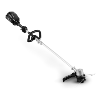
The design of your trimmer is to power the wheels in the forward direction
only. Read and follow these directions and notes carefully when installing a
wheel.
Before performing any adjustment, maintenance procedure or inspection,
stop the engine, wait five (5) minutes to allow parts to cool and disconnect
the spark plug wire, keeping it away from the spark plug.
Before performing any adjustment, maintenance procedure or inspection,
stop the engine, wait five (5) minutes to allow parts to cool and disconnect
the spark plug wire, keeping it away from the spark plug.
Remove Locknut
Figure 40
 Loading...