12
Dräger Flame 3000
3.2.2 Electrical
CAUTION
The Dräger Flame 3000 must be properly grounded. Failure to
do so may cause electrical interference in the equipment.
Do not over tighten the cable glands. Metric cable entries are
tted with an internal stop that results in the threads being
visible after assembly. Over tightening may result in damage
to both the cable entry and the gland.
NOTICE
A 2 m helix should be allowed in the Dräger Flame 3000
cabling. This allows the detector to be repositioned if local
obstructions, such as pipework and cable trays, block the
detector’s view of the local hazard.
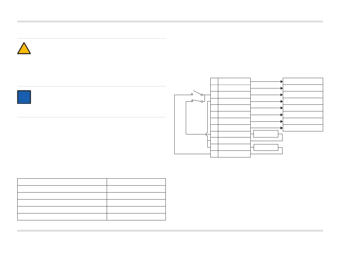
The Dräger Flame 3000 can operate via a standard 3 or 4
wire termination and has two types of alarm output available
simultaneously:
• 4 – 20 mA
• Relay (alarm and fault)
The 4 – 20 mA signal outputs are as follows:
!
i
internal connections Flame 3000 terminal
field connections
1 (+ 24 V)
2 (0 V)
3 (A)
4 (B)
5 (4 – 20mA)
6 (0 V)
7 (+ 24 V)
8 (0 V)
9 (C)
10 (B)
11 (B)
12 (Alarm)
+ 24 Vdc
0 Vdc
To fire panel
To fire panel
4 – 20mA source
0 Vdc
+ 24 Vdc
0 Vdc
End-of-line
resistor
Alarm
Alarm relay
(normally open)
Fault relay
(normally
closed)
Event Output
Power/detector fault
0 mA
Optical fault 2 mA
Healthy condition 4 mA
Alarm 18 mA
Over-range 21 mA
The internal connections of the alarm and fault relay contacts and
jumpers are shown in below. Each eld connection is also shown on
this illustration for clarity.
The end-of-line and alarm resistances are to be calculated based on
the requirements of the control system.
3880
1. Isolate all associated power supplies. Ensure that they remain
isolated until required for commissioning.
2. Connect the enclosure earth stud to a local ground point.
3. Remove the blanking plug(s) from the enclosure gland entries.
4. Fit the cable gland to the enclosure. Ensure that it is tted with a
minimum of ve threads inside the enclosure and with the ingress
protection seal washer tted at the bottom of the thread. Tighten the
gland to a torque between 15 – 20 Nm (11 – 15 lbf ft).
5. Loosen the set screw located in the rear enclosure cover. Unscrew
and remove the rear enclosure.
Use