’
.;,,,:,,
‘;
/’
_
.-.-.-.-:i:&..
.A.!.i
Mounting
and
Usage
of
Holder
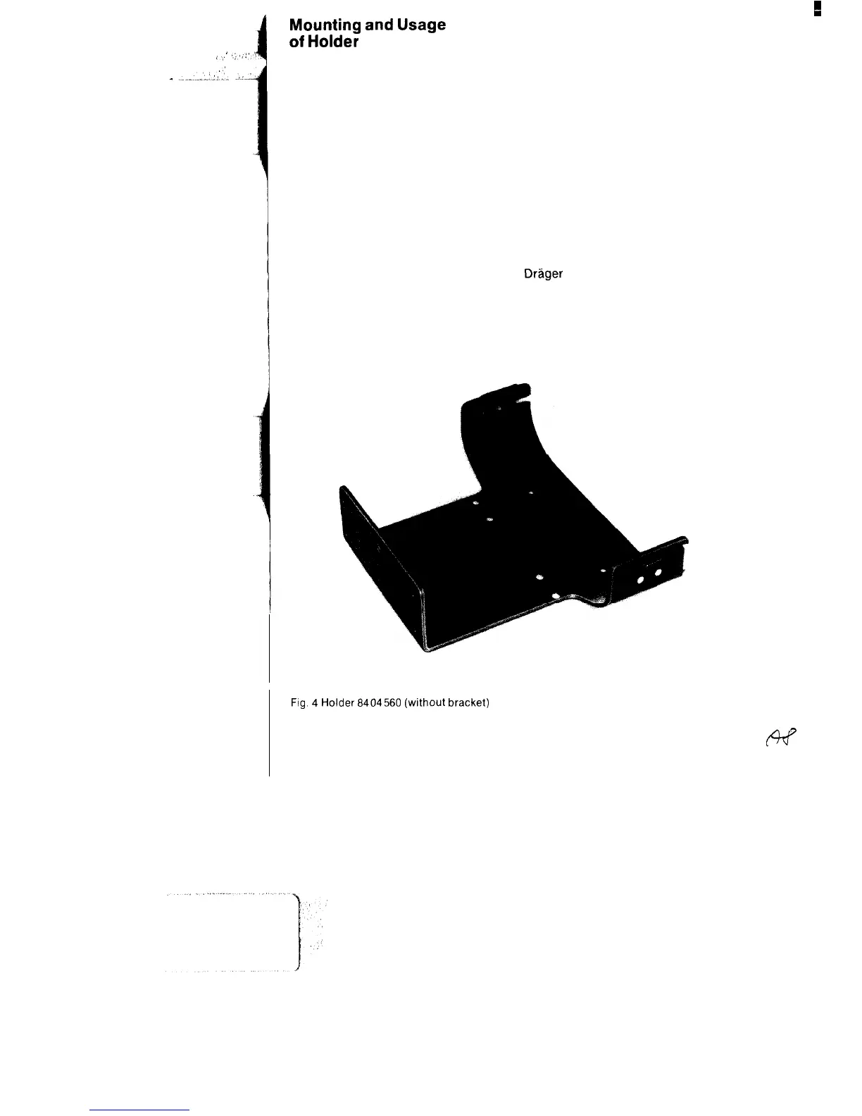
The Oxylog is secured in position in the
rescue vehicle by way of the holder
8404560 (Fig. 4).
The screws for attaching the basic
element are provided.
Mounting of holder
The basic element 16 is provided with
sufficient holes for the fastening screws.
At least 3 screws (with maximum
possible spacing between them) are to
be used in each case. The installation
location is arbitrary.
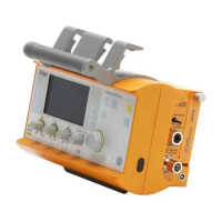
Insertion of Oxylog into holder
Push device into holder such that stems
of two studs 7 on housing slide into slots
Fig.
4
Holder
6404560
(without
bracket)
6
16a of holder. Studs must engage in
hole in brackets 17.
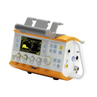
Press on brackets 17 to ensure that the
device is firmly secured in position in
the holder.
The guide stud 19 secures the device on
the back. Fig. 5 illustrates the Oxylog in
position in the holder.
Removing Oxylog
Pressing open the two brackets 17
releases the studs 7 and enables the
device to be removed from the holder.
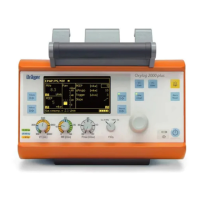
Holder with rail bracket (Fig. 6)
The holder is used for attachment to the
Drager
wall rail system (10 x 25 mm
section).
Handling is the same as for the holder
8404560.