Maintenance
Dräger Polytron 2000 13
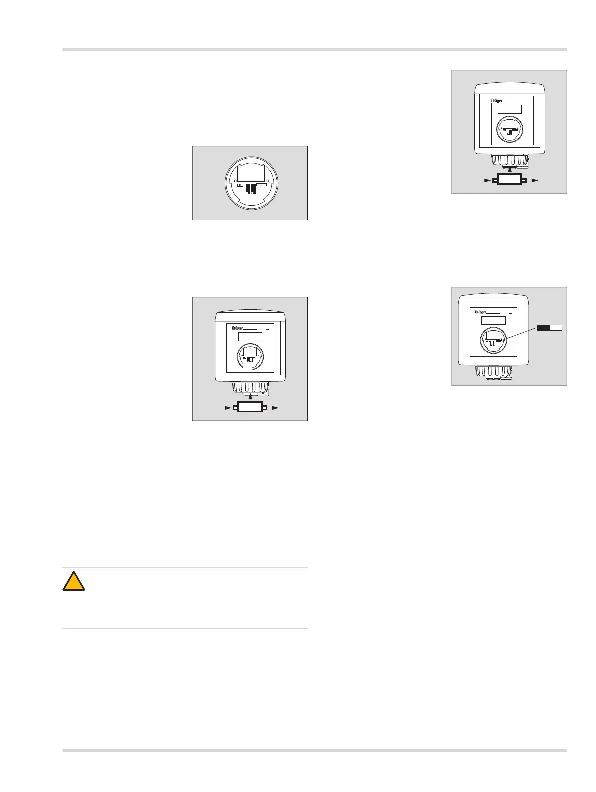
If jumper J1 is placed on the two left pins, only the factory
calibration of the sensor can be used.
If jumper J1 is placed on the two right pins, it can be calibrated
with calibration gas.
Controls
Potentiometer (7) (left) for
calibration of the zero-point.
Potentiometer (8) (right) for
calibration of the sensitivity.
6.2.1 Calibrating zero-point
For all sensors except sensor for oxygen:
If the ambient air is free from target gas and other interference
gases, the zero-point calibration can be performed without
using nitrogen (zero gas) or
1. use calibration adapter (1).
2. Set maintenance switch
to maintenance position,
see page 12.
3. Apply nitrogen via the
calibration adapter at a flow
rate of 0.5 L/min. Synthetic
air can also be used, except
for oxygen sensors.
4. Wait for a stable measured
value – approx. 3 minutes.
Follow the instructions in
the sensor data sheet.
5. Set the potentiometer (2)
for zero-point so the display shows 0.
For oxygen sensors:
The zero-point cannot be calibrated for these sensors.
The zero-point is simply checked.
1. Shut off the calibration gas and remove the calibration
adapter.
2. Set maintenance switch to measuring position, see
page 12.
6.2.2 Calibrating sensitivity
The recommended calibration gas concentration for optimum
accuracy is 40 to 80% of the full scale reading.
1. Use calibration adapter (1).
2. Set maintenance switch to
maintenance position, see
page 12.
3. Apply calibration gas via the
calibration adapter at a flow
rate of 0.5 L/min.
4. Wait for a stable measured
value – approx. 3 minutes.
Follow the instructions in
the sensor data sheet.
5. Set the sensitivity of the
potentiometer so the
display shows the
concentration of the calibration gas.
6. Shut off the calibration gas and remove the calibration
adapter.
7. Wait until the measured value is below the alarm threshold
set in the central controller. Otherwise an alarm will be
triggered if the maintenance switch is set to the measuring
mode position immediately after calibration.
8. Set maintenance switch (1)
to measuring position,
left position. The 4 to 20 mA
output switches to
measuring mode.
9. Insert the front cover into
the service port and turn it
clockwise (approx. 60°) with
a hexagonal wrench to
close it.
CAUTION
Never inhale the calibration gas - health hazard!
Observe the hazards arising from the calibration gas,
the hazard information and the safety advice.
For example, see the safety data sheets for information.