How to fix faulty zero-point on Dräger Transmitter?
- AAmber BakerJul 27, 2025
To correct a faulty zero-point on the Dräger Transmitter, perform a zero-point calibration.
How to fix faulty zero-point on Dräger Transmitter?
To correct a faulty zero-point on the Dräger Transmitter, perform a zero-point calibration.
How to fix a faulty span calibration on Dräger Transmitter?
To correct a faulty span calibration that was performed on the Dräger Transmitter, perform a new span calibration.
What to do if my Dräger Transmitter has a serious device fault?
If the Dräger Transmitter displays a serious device fault, it is recommended to have it checked by DrägerService®.
What to do if Dräger Transmitter shows a device fault?
If the Dräger Transmitter has a device fault, check the contacts. Should the issue persist, have the device checked by DrägerService.
What to do if Dräger Transmitter has a serious data error?
If the Dräger Transmitter displays a serious data error, reset the device to factory settings. If the fault continues to occur, have the device checked by DrägerService.
How to fix a Dräger Transmitter device fault?
If the Dräger Transmitter displays a device fault, restart it. If the fault continues, have the device checked by DrägerService.
What to do if 4-20 mA interface cable is not connected to Dräger Transmitter?
To address a 4-20 mA interface cable that is not connected on the Dräger Transmitter: Disconnect the power supply, connect the 4-20 mA interface, and then reconnect the power supply. For operation without a controller, connect terminal 3 with terminal 4.
Safety guidelines for product use, handling, and maintenance.
Explains the meaning of warning, caution, and notice icons used in the document.
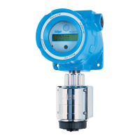
Overview of the explosion-proof device and its version with e-Box.
Explains the working principle of the DrägerSensor EC.
Describes the purpose, application, and operating conditions for the device.
Lists certifications and explains device markings.
Crucial factors and considerations for installing the device.
Details limitations and impedance limits for HART communication.
Guidelines for mounting and wiring the device without e-Box.
Wiring instructions for devices equipped with relay modules.
Instructions for installing the device with an e-Box.
Steps for correctly installing the sensor unit.
Procedures for mounting remote EC sensing heads and connecting them.
Steps for connecting to Dräger control systems, PCs, and installing software dongles.
Basic principles, menu navigation, and parameter changes.
Explains the device display and indicator LEDs.
Interpretation of device symbols and accessing information.
Switching between menus, password entry, and measurement mode operation.
How analog signals (4-20 mA) represent measurements.
General steps for calibrating the device, including zero point calibration.
Procedures for span calibration and automatic calibration.
Overview of accessing device and sensor information.
Overview of calibration options.
Overview of device configuration settings.
Overview of communication interface settings.
Overview of sensor configuration options.
Overview of data logger configuration.
Accessing details on device settings, warnings, faults, and modules.
Provides details on the last and next calibration dates.
Querying the datalogger status and viewing measured values.
Managing SIL lock and general device configuration.
Configuring alarm relays, LEDs, and alarm limits.
Testing alarms, changing passwords, and setting date/time.
Configuring display language and assigning functions to keys.
Resetting to factory defaults, deactivating dongles, and adjusting display.
Configuring communication interfaces, primarily HART.
Detailed configuration for the HART interface, including Unique Identifier and tag names.
Configuring analog output signals like fault, warning, and maintenance currents.
Setting various analog signal currents and performing interface tests.
Changing sensors, enabling auto-CAL, sensor tests, sensor lock, and gas settings.
Resetting sensor parameters and setting calibration intervals.
Configuring and clearing the datalogger.
Table listing fault numbers, causes, and remedies.
Table listing warning numbers, causes, and remedies.
Recommended maintenance schedules and sensor changing procedure.
Procedure for replacing the main electronic components.
Guidelines for proper disposal of the device and sensors.
Technical details on signal output, supply voltage, and housing.
Operating conditions and environmental factors affecting performance.
Specifications for torques, terminals, and default device settings.
List of settings that cannot be modified by the user.
Lists available Dräger Polytron 8000 device models.
List of optional accessories for the device.
List of available replacement components.
EU Declaration of Conformity and EC type examination certificate.
Lists applicable directives and standards for the product.
Information on production quality assurance.
Specifies hazardous area classifications for installation.
Ratings for non-intrinsically safe field wiring.
Requirements for intrinsically safe cabling.
Diagrams of device configurations and intrinsically safe cabling.
| Ingress Protection | IP66/67 |
|---|---|
| Gas Detection | Electrochemical, Infrared, Catalytic |
| Display | Backlit LCD |
| Housing Material | Aluminum or stainless steel |
| Temperature Range | -40 to +65 °C |
| Humidity Range | 0% to 95% RH (non-condensing) |
| Power Supply | 18-30 V DC |
| Output Signal | 4 to 20 mA, HART |
| Certifications | ATEX, IECEx |
| Measuring Range | Depends on gas type |
| Weight | Approx. 1.6 kg (Aluminum), 3.2 kg (Stainless Steel) |
