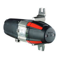
What to do if Dräger Polytron 8100 has a faulty zero calibration?
- Bbrandon03Aug 16, 2025
If the Dräger Transmitter has a faulty zero calibration, perform a zero calibration.
What to do if Dräger Polytron 8100 has a faulty zero calibration?
If the Dräger Transmitter has a faulty zero calibration, perform a zero calibration.
What to do if Dräger Polytron 8100 has a faulty span calibration?
If the Dräger Transmitter has a faulty span calibration, perform a span calibration.
What to do if my Dräger Polytron 8100 shows a fault?
If the Dräger Transmitter shows a fault, try resetting it to factory default settings. If the fault persists, it may need to be checked by DrägerService due to various potential causes.
What to do if Dräger Polytron 8100 Transmitter has fault #001 #003 #004 #005 #011 - #014 #020 - #024 #043 #060 #067?
If the Dräger Transmitter has one of these faults, it should be inspected by DrägerService due to the variety of potential causes.
What to do if Dräger Polytron 8100 shows instrument fault #076 #080 - #084?
If the Dräger Transmitter shows a fault, start by checking the electrical connections. If the issue continues, it might need to be inspected by DrägerService due to an instrument fault.
What to do if my Dräger Transmitter is not detecting any sensor?
If the Dräger Transmitter isn't detecting any sensor, first check the connections. If the problem continues, the instrument may need to be inspected by DrägerService.
What to do if Dräger Polytron 8100 Transmitter displays fault #137?
If the Dräger Transmitter displays fault #137, try cycling the power. If the fault persists, the instrument should be checked by DrägerService.
How to fix Dräger Polytron 8100 fault #010?
If the Dräger Transmitter displays fault #010, disconnect the power supply, connect the 4 to 20 mA interface cable, and then reconnect the power supply. If using it as a stand-alone instrument without a central controller, wire pin 3 to pin 4.
Why does my Dräger Polytron 8100 show fault #090?
If fault #090 appears on the Dräger Transmitter, it means the sensor lock function is activated and a sensor with a different part number has been connected. Use a sensor with the same part number or disable the sensor lock function.
What to do if Dräger Transmitter has fault #105?
If the Dräger Transmitter has fault #105, it should be inspected by DrägerService due to an instrument fault.
Provides essential safety precautions and user responsibilities for operating the instrument.
Explains the meaning of DANGER, WARNING, CAUTION, and NOTICE icons used in the manual.
Introduces the explosion-proof instrument and its variant with an increased safety wiring compartment.
Specifies the hazardous area classifications (zones and divisions) and environmental conditions for operation.
Details the instrument's power supply, display, LEDs, and output signals (analog/HART).
Covers crucial factors for effective system performance and installation details.
Lists limitations and requirements for instrument installation, including power and environmental factors.
Provides impedance ranges for the signal loop based on operating mode and supply voltage.
Details wiring for power, signal, and optional relays for installations without a docking station.
Explains how to connect power and signal wires to the 5-way pin connector.
Describes the wiring and precautions for the optional relay board.
Provides steps for physically installing the sensor into the instrument housing.
Steps for installing the EC sensing head into its housing.
Instructions for connecting the instrument to a Dräger controller.
Explains how to connect the instrument to a PC using an IR interface.
Covers the start-up sequence, warm-up period, and normal display of gas concentration.
Explains the 4-20 mA current output and its relation to gas concentration.
Describes the information shown on the display and the meaning of different LED indicators.
Lists the symbols for LED indicators and their corresponding states (alarm, fault, power).
Illustrates the information screens for instrument and sensor details.
Describes how to access the Quick Menu for status and settings retrieval.
Explains how to enter and manage the 4-digit alphanumeric password for menu access.
Details how to navigate menus and change parameter values or statuses.
Explains how to exit the menu and return to normal operation.
Displays warning messages in plain text with corresponding numbers.
Displays fault messages in plain text with corresponding numbers.
Shows the date of the last calibration performed on the sensor.
Step-by-step guide for performing zero calibration on the sensor.
Step-by-step guide for performing span calibration using calibration gas.
Automates the calibration sequence, reducing manual steps.
Configures alarm behavior, relay energization, latching, and acknowledgement modes.
Allows changing passwords for calibration and settings access.
Sets the instrument's date and time, crucial for many functions.
Resets the instrument to its factory default settings.
Deactivates SW dongles for safe removal or if faulty.
Allows adjustment of display contrast and mode, and performs a display test.
Configures HART interface settings like polling address, unique identifier, tag, and Dräger REGARD protocol.
Sets special signal currents (fault, warning, maintenance) and controls warning signal transmission.
Placeholder for future Profibus address settings.
Configures warning signal transmission and maintenance signal type (static/dynamic).
Sets current values for warning and maintenance signals.
Adds an offset to the analog output for controller synchronization.
Describes how to change the sensor without interrupting operation or losing settings.
Configures gas type, measurement range, units, and sensor type.
Sets analog output current for normal operation, concentration, and fault conditions.
Enables automatic calibration and sensor self-tests for instrument verification.
Activates sensor lock and selects sensor type for specific models.
Configures gas type, range, units, and resets sensor parameters to factory defaults.
Enables or disables periodic sensor self-tests.
A function specific to Polytron 87X0 using the PIR 7X00 sensor.
Enables or disables the data-logger function.
Configures sampling time, peak/average storage, trigger value, and stack/roll mode.
Deletes all stored data from the data-logger.
Outlines intervals for commissioning, 6-monthly checks, and sensor changes.
Details the importance and procedure for instrument calibration.
Step-by-step guide for performing span calibration using calibration gas.
Lists fault numbers, their causes, and recommended remedies.
Step-by-step guide for replacing the main electronics of the instrument.
Lists factory default settings for various menu parameters and their configurable ranges.
Provides guidelines for the disposal of electrical and electronic equipment and sensors.
Lists various certifications and approvals (ATEX, IECEx, UL, CSA) for the instrument.
Details technical specifications for the DrägerSensor O2.
Specifies the response times (t0-20, t0-90) of the instrument.
Defines the analog output signals for normal operation, faults, and maintenance.
Describes the HART communication protocol and its parameters.
Specifies operating voltage, current, cable specs, enclosure material, display size, and weight.
Specifies torque and wire size for field wiring terminals.
| Display | LCD with backlight |
|---|---|
| Sensor Technology | Electrochemical, Infrared, Catalytic Bead |
| Output Signal | 4 to 20 mA, HART |
| Ingress Protection | IP66 |
| Housing Material | Stainless steel or Aluminum |
| Gas Types | Combustible gases, toxic gases, oxygen |
| Approvals | ATEX, IECEx |
| Communication | HART |
| Measurement Range | Depends on sensor type |
| Certifications | CE |
| Power Supply | 12-30 V DC |
