Menu
Dräger Polytron 8100 23
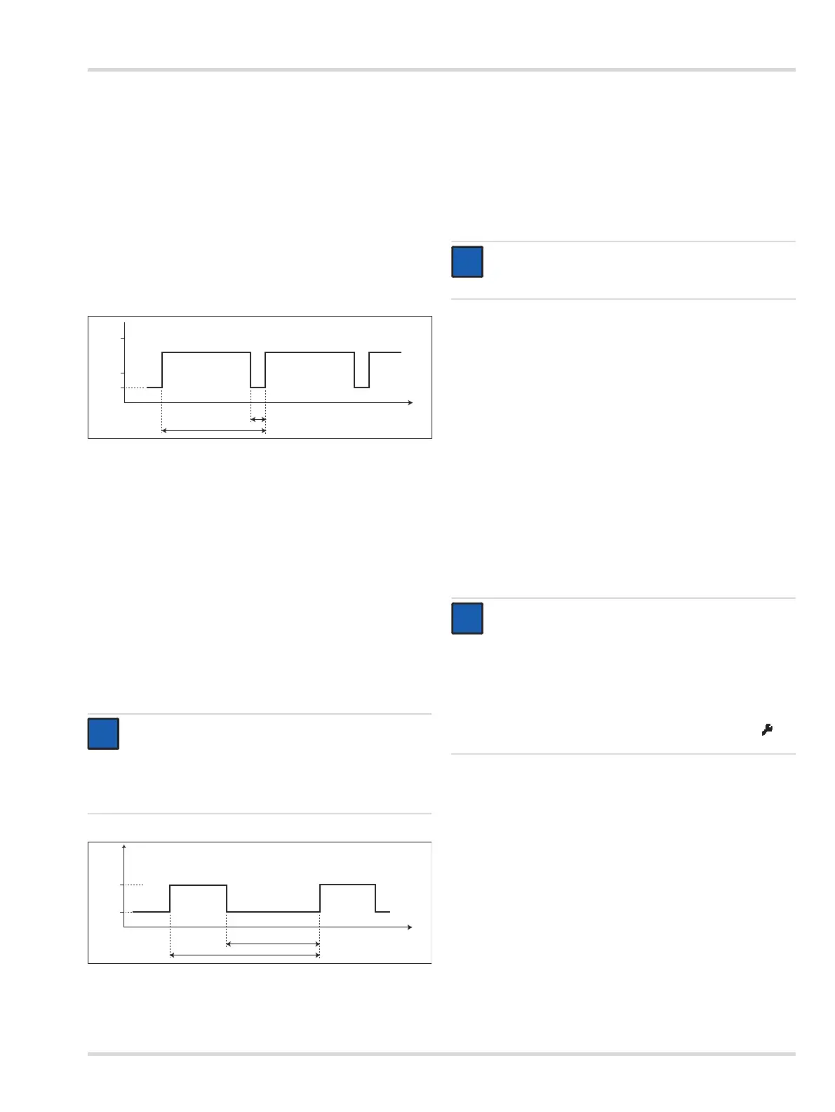
Warning interval
This function defines the time interval for the warning signal.
Select Settings > Communication > Analog interface >
Warning interval and confirm.
Select the line for editing T1 and confirm.
Set the time and confirm.
The setting for Time T1 is displayed.
Select Next and confirm.
Select the line for editing T2 and confirm.
Set the time and confirm.
The setting for Time T2 is displayed.
Select Confirm and confirm with [OK].
Warning current
This function defines the current for the warning signal.
Select Settings > Communication > Analog interface >
Warning current and confirm.
Select the line for editing the current and confirm.
Set the current and confirm.
The setting for the warning current is displayed.
Select Confirm and confirm with [OK].
Maintenance signal
This function selects the type of maintenance signal.
Select Settings > Communication > Analog interface >
Maint. signal and confirm.
Select static or dynamic signal type and confirm.
Maintenance current
This function defines the current for the maintenance signal.
Select Settings > Communication > Analog interface >
Maint. current and confirm.
Select the line for editing the current and confirm.
Set the current and confirm.
The setting for the maintenance current is displayed.
Select Confirm and confirm with [OK].
Beam block on or off
This function is only available for Polytron 87X0 (using the
sensor PIR 7X00).
Analog offset
This function adds an offset to the analog output. The offset is
constant over the entire range of the analog signal.
This function is essential for an installation where the analog
current at the instrument differs from the current at the central
controller.
Select Settings > Communication > Analog interface >
Analog offset and confirm.
Select the line for editing the offset (range: -0.2 to 1.5 mA)
and confirm.
Set the current and confirm.
The setting for the analog offset is displayed.
Select Confirm and confirm with [OK].
Test functions for the analog interface
NOTICE
The static signal type is a constant current. However,
the current value can be configured.
The dynamic signal type is a square wave signal with
the following characteristics.
0533300.eps
t
[s]
T
1
Messwert
4
20
[mA]
T
2
3
0633300.eps
t
[s]
1,1
[mA]
0,7
5
3
NOTICE
The maintenance current can only be set if the
maintenance signal has been set to static.
NOTICE
These functions change the current of the analog
interface for test purposes (e.g. to check the
programming of the central controller). It might be
necessary to inhibit the alarms at the central controller
to avoid false alarms. After exiting these functions, the
currents, if changed, will automatically return to the
maintenance signal.
During the test, the maintenance symbol [ ] is
displayed.
i
i
i
i