14 Dräger Polytron 8100
Operation
4 Operation
4.1 Normal operation
Switch power supply on.
The instrument will go through a start-up sequence (LCD / LED
test, software version, and initialization) and start the warm-up
period. The display shows that the sensor will be ready for
measurement in hh:mm:ss (countdown) and the instrument
transmits the maintenance signal, see Section 10.3 on
Page 41.
After the warm-up period, the instrument goes into normal
operation. The display shows the current gas concentration,
the selected gas and the units of measurement. The green
LED is lit.
4.1.1 Analog signals
The current output of the instrument during normal operation is
between 4 and 20 mA and is proportional to the detected gas
concentration.
Polytron 8000 uses different current values to indicate various
modes of operation. The factory default settings are user
adjustable for application specific requirements, see Section 7
on Page 34. This follows the NAMUR recommendation NE43.
4.1.2 The display and LEDs
In normal operation, the display shows the measured gas
concentration, the selected gas and the unit of measurement.
The green LED is lit.
The following symbols may also be displayed:
" ", when the measuring range is exceeded
" - - - - " and " X " when a fault has been detected. The
yellow LED is lit, see Section 6.3 on Page 31.
"SIL", when SIL status is activated.
If the optional relay board is installed:
When the first alarm (pre alarm) has been triggered the red
LED blinks in single mode. The A1 relay is asserted.
When the second alarm (main alarm) has been triggered
the red LED blinks in double mode. The A2 relay is
asserted.
If the A2 is configured as acknowledgeable, and the A1 is
configured as non-acknowledgeable, then, when an A2
alarm occurs, the red LED will blink in double blink A2
mode. After the alarm is acknowledged, the red LED will
blink in single blink mode to indicate A1 is still active.
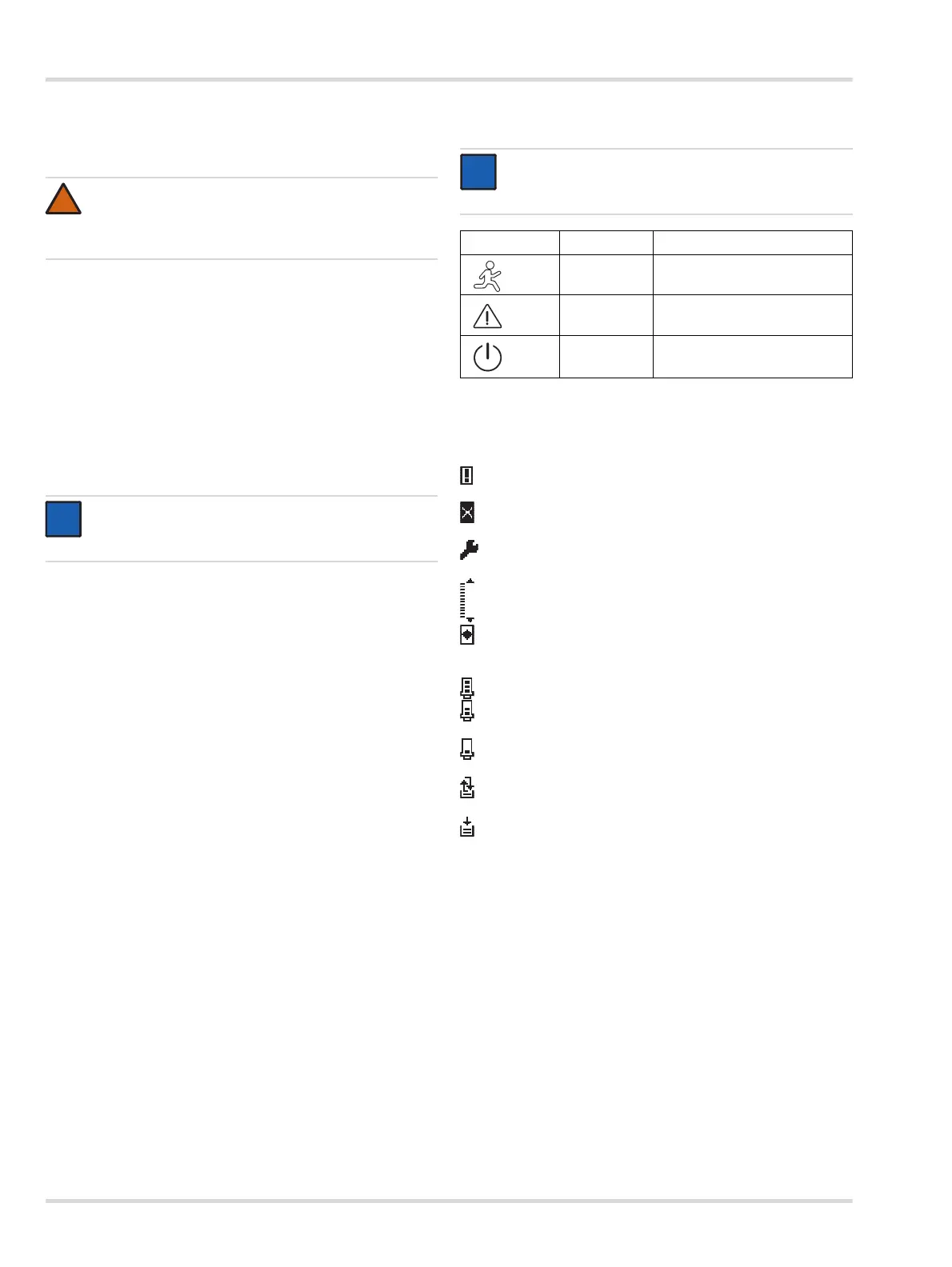
4.1.3 The LED symbols
4.1.4 Status indicators in the display
The following status indicators may appear on the right side of
the display.
4.2 Activating the Info mode
No password required.
The Info mode is used to show instrument relevant information.
This will not interrupt the normal operation of the instrument.
Tap and hold [UP] for more than 3 seconds.
The instrument information is shown on several screens.
No changes can be made.
Tap [UP] / [DOWN] to switch between the screens.
The Info mode can be exited at any time by tapping [OK].
If no key is tapped within 30 seconds, the instrument will
automatically return to normal operation.
WARNING
Before leaving the instrument for normal operation,
check the configuration and calibration for the proper
settings.
NOTICE
The correct date and time settings are important for
many functions see Section 5.7.3 on Page 20.
NOTICE
The alarm triggering function is only available when
the optionally integrated relay module is used.
Symbol LED Description
red Alarm triggered
yellow Fault
green
Power ON
Normal operation
Warning message available – to display warnings, see
Section 5.2.1 on Page 18.
Error message available – to display errors, see
Section 5.2.2 on Page 18.
Maintenance signal is transmitted, see Section 5.8.2 on
Page 22.
Measuring range of analog interface exceeded
Measurement less than range of analog interface
Analog interface is set to a fixed value (e.g. Multidrop HART
communication) and is not transmitting any measurement
signal.
"Preventive" maintenance: The sensor is ready for operation.
"Preventive" maintenance: The sensor is ready for operation
but is close to the end of its life cycle.
"Preventive" maintenance: The sensor is still ready for
operation but should be changed as soon as possible.
The data-logger is active in Roll mode.
To activate/deactivate, see Section 5.10.2 on Page 27.
The data-logger is active in Stack mode.
To activate/deactivate, see Section 5.10.2 on Page 27.
SIL
SIL is activated (refer to the Polytron 8000 Safety Manual
part number 9033307).
i
i