Installation
Dräger Polytron 8100 9
3.4 Mechanical installation
Use the drilling template for mounting on a flat surface.
The mounting surface should be even.
Dräger recommends using M6, 1/4” bolts with hex socket
caps.
The instrument must be accessible for maintenance (e.g.
calibration).
The future use of accessories and maintenance equipment
must be kept in mind.
The access of the gas or vapor to the sensor must not be
obstructed.
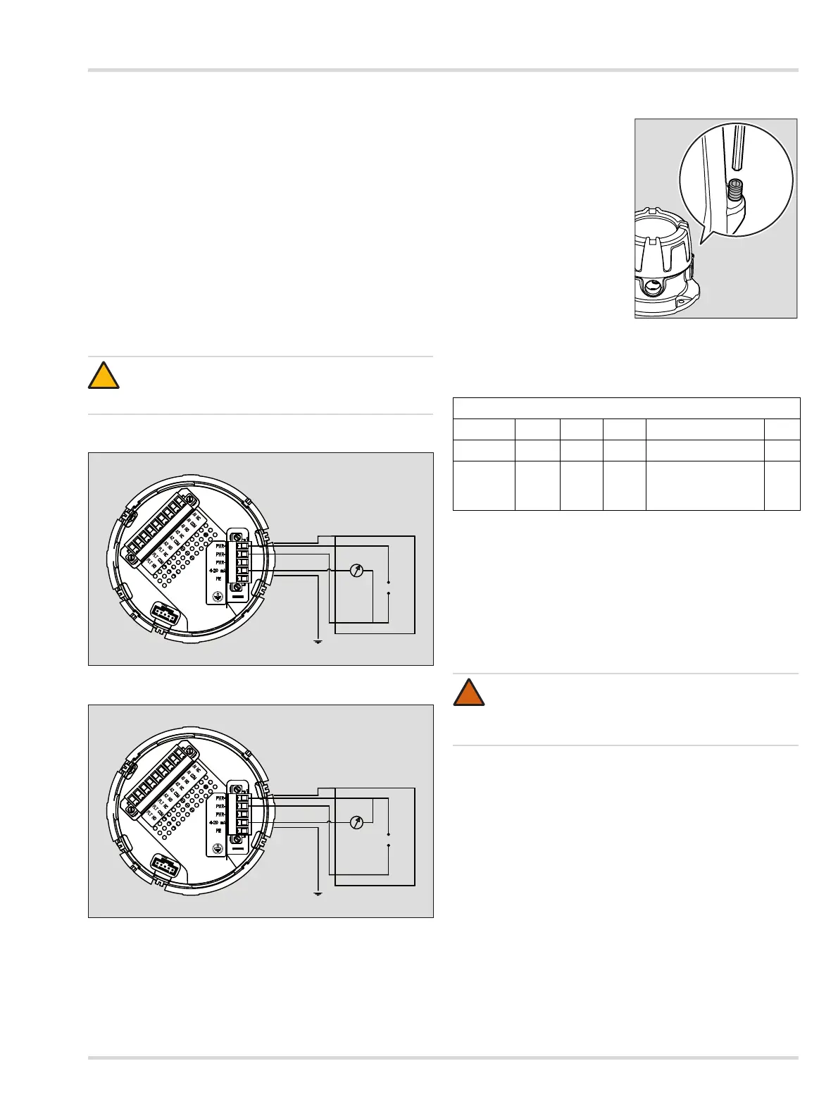
3.5 Electrical installation without Docking
Station
Connection diagram for operation as a current source
Connection diagram for operation as a current sink
3.5.1 Power and signal wiring
Loosen set-screw and un-
screw lid from instrument.
Lift the handle and pull-out
the bucket with the main
electronics.
Turn bucket over and pull
off the 5-pin connector.
Connect the three wires for
power and signal to the
appropriate terminal as
indicated in the following
wiring table and figure.
Fasten terminal screws
with the correct torque
according to the table
tightening torque and wire size for field wiring terminal, see
Section 10.9 on Page 42.
If operated as a stand-alone instrument, wire pin 3 to pin 4.
Plug connector back into socket and tighten screws.
The cable shielding should only be connected at the
controller.
Place bucket back into the enclosure.
Screw the lid back on, until it is seated (see Section 10.8
on Page 42) and tighten set-screw.
3.5.2 Relay option
If the relay option has been installed, the wires for the alarm
devices will be connected to the 9-pin connector. A piece of
wire insulation (heat shrink tube) and rubber boot are supplied
for extra protection for relay wires.
Turn bucket over and pull off the 9-pin connector.
Cut the heat shrink tube as needed and slide over the relay
wires before insertion into the 9-pin connector.
Position the heat shrink tube at the edge of wire insulation
and use a heat gun to shrink the tubing securely onto wire
insulation.
Slide rubber boot over the wires.
CAUTION
Ensure wiring for relays and connections for sensor
are made before applying power.
5-way Pin connector (power and signal)
Pin 1 2 3 4 5
Mark PWR+ PWR- PWR- 4-20 mA PE
Function V+ V- V- 4 to 20 mA signal
(Operation as
source or sink)
PE
WARNING
At voltages >30 V AC or >42.4 V DC, the relay cables
must be enclosed in protective tubing, or double-
insulated cables must be used.
00933300.eps