10 Dräger Polytron 8100
Installation
Connect the wires for alarm 1 (pre alarm), alarm 2 (main
alarm) and fault alarm to the terminals, as indicated in the
following wiring table. Fasten terminal screws with the
correct torque according to the table tightening torque and
wire size for field wiring terminals, see Section 10.9 on
Page 42.
With factory default settings and during normal operation,
the relays are energized. This provides “fail-safe”
operation. The terminal designators indicated in the
following wiring table are shown as factory default and
normal operation mode, see Section 7 on Page 34.
Plug connector back into socket and tighten screws.
Put rubber boot over connector.
NO = Normally open, NC = Normally closed, C = Common
3.6 Electrical installation with Docking
Station
Installing this configuration is a two-step process.
First, the Docking Station is mounted and connected to the
field wires. Second, the main instrument enclosure with the
electronics and sensor is attached to the Docking Station.
The Docking Station can be pre-mounted, wired and sealed
with the supplied cover. Once the site is ready for
commissioning, the instrument is then hooked up to the
Docking Station and taken into operation; avoiding that the
instrument is damaged during the construction phase.
The connection between the Docking Station and the main
instrument is realized via a ‘feed-through’. Depending on the
instrument selected, there are 2 types of feed-through.
3 wire for power (part number 4544182)
9 wire for power and relay (part number 4544169)
3.6.1 Field wiring
For field wiring of Docking Station refer to Instructions for use
9033242.
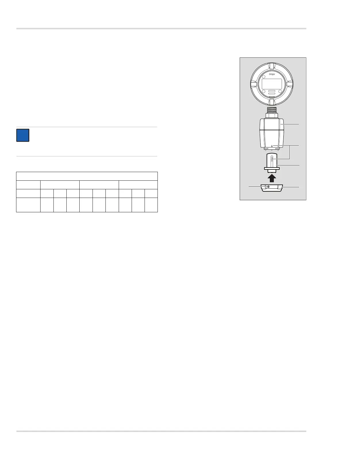
3.7 Installing sensor
Loosen set-screw (2), 2mm Allen screw.
Unscrew bayonet ring (3)
and remove blank.
Remove sensor from
packaging.
Insert sensor (4) into the
opening. The Dräger logo
on the sensor must point
to the mark on the sensing
head housing (5).
Lock sensor with bayonet
ring.
Tighten set-screw (2).
Mandatory for Zone 22
installations.
NOTICE
To ensure that a fault is recognized - without having to
look at the instrument - an alarm device must be
connected to the fault relay.
9-Pin connector (relays)
Fault relay A2 relay A1 relay
Pin 123456789
Mark FLT
NO
FLT
C
FLT
NC
A2
NO
A2
C
A2
NC
A1
NO
A1
C
A1
NC