Maintenance
Dräger Polytron 8100 33
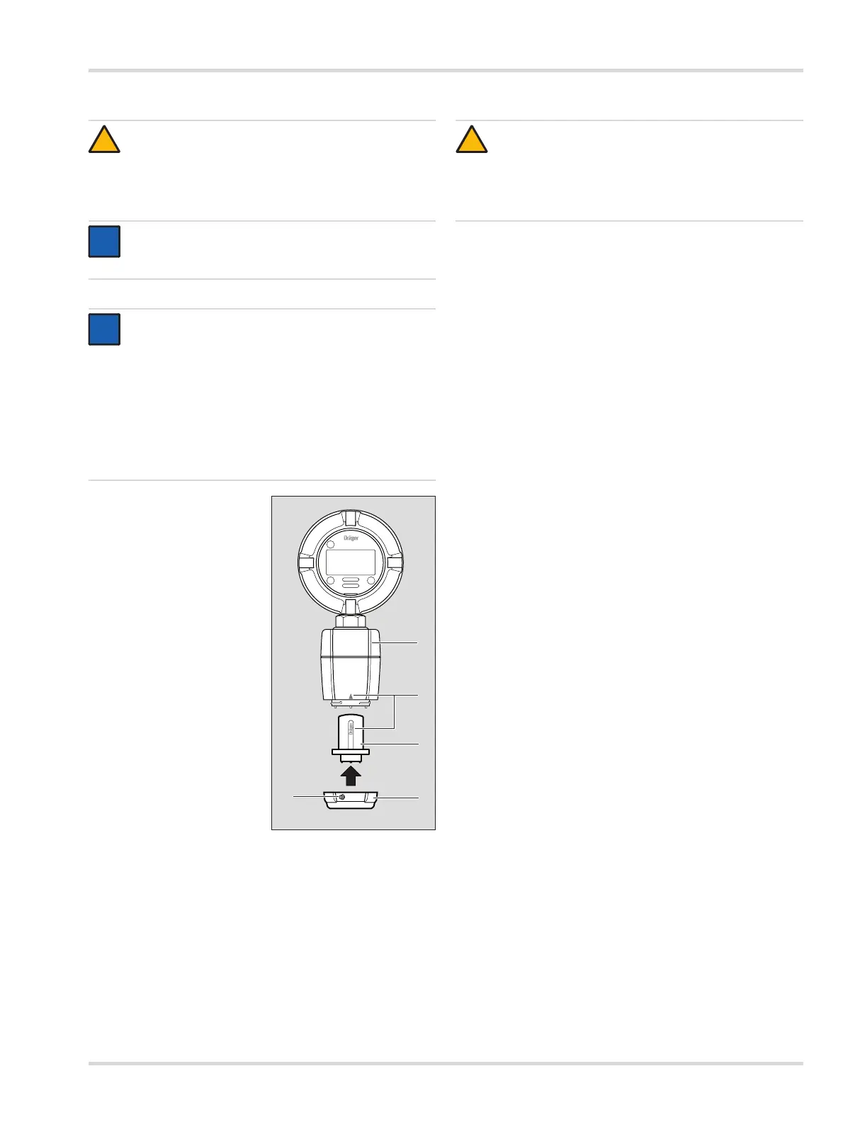
6.4 Replacing the sensor
To replace the sensor:
Select Settings > Sensor
> Sensor change and
confirm.
Loosen set-screw (2)
2 mm Allen screw.
Unscrew bayonet ring (3).
Remove sensor from
packaging.
Insert sensor (4) into the
opening. The Dräger logo
on the sensor must point
to the mark on the sensing
head housing (5).
Lock sensor with bayonet
ring.
Tighten set-screw (2).
Mandatory for Zone 22
installations.
If necessary, apply the
label included with the
sensor to the instrument.
This identifies the gas type
from a distance, even if the power has failed.
Calibrate instrument, if necessary (see Section 6.2 on
Page 28).
Check the installation requirements and instrument for SIL
status (see Section 5.6 on Page 18).
6.5 Replacing the main electronics
To replace the main electronics:
Turn off power to the instrument or declassify the area
according to local regulations.
Loosen set-screw and unscrew lid from instrument.
Lift the handle and pull out the bucket with the main
electronics.
Turn bucket over and pull off the power, relay and sensor
connectors.
Replace the main electronics.
Plug the power, relay and sensor connectors back into
appropriate sockets and tighten screws.
Place bucket back into the enclosure.
Screw the lid back on until it is seated (see Section 10.8 on
Page 42) and tighten set screw.
Apply power to the instrument.
Check all settings and parameters.
Calibrate instrument, if necessary (see Section 6.2 on
Page 28).
Check the installation requirements and instrument for SIL
status (see Section 5.6 on Page 18).
CAUTION
Always test a newly installed sensor with target gas to
verify proper operation
If the sensor is replaced, all settings and parameters
must be checked for correctness.
NOTICE
The sensor can be replaced in the hazardous,
classified area, without interrupting the power supply.
NOTICE
If a sensor of the same type (same part number) was
previously installed, the instrument specific
configuration is retained (gas type, measurement
range, test gas, calibration interval, etc.)
Otherwise the factory default settings of the new
sensor (see Instructions for Use for the sensor) are
uploaded and will overwrite the instrument specific
configuration.
This can be prohibited if the sensor lock function (see
Section 5.9.4 on Page 25) is activated.
CAUTION
Always test a newly installed main electronics with
target gas to verify proper operation
If the main electronics is replaced, all settings and
parameters must be checked for correctness.
!