Settings menu
Dräger Polytron 8000 23
Setting the maintenance current
This function is used to set the current for the maintenance
signal on the analog interface.
1. Select Settings > Communication > Analog interface >
Maint. current and confirm.
2. Select the current line for the entry and confirm.
3. Set the current and confirm.
The setting for the maintenance current is displayed.
4. Select Confirm and confirm.
Setting the 4 to 20 mA offset
This function adds an adjustable offset current to the analog
interface. The offset is constant over the entire range of the
output signal.
1. Select Settings > Communication > Analog interface >
Analog offset and confirm.
2. Select the current line for the entry (max. range: –0.2 to
1.5 mA) and confirm.
3. Set the current and confirm.
The setting for the 4 to 20 mA offset is displayed.
4. Select Confirm and confirm.
Test functions for the analog interface
Setting current signals
Using this function, various currents in the range from 0 to
22 mA can be set on the analog interface.
1. Select Settings > Communication > Analog interface >
Set current signal and confirm.
2. If the alarm in the control unit is disabled, confirm the
message suppress all alarm settings.
3. Select the current line for the entry and confirm.
4. Set the current and confirm.
The setting for the current is displayed.
5. Select Next and confirm.
6. Select Set current out or Current off and confirm.
7. Select Next and confirm. The function is terminated.
8. After the alarm settings in the control unit have been re-
enabled, confirm the Enable all alarm settings message.
Setting the concentration
This function is used to set various concentrations in the range
between 0 and 100 % of the selected unit of measure.
The current output is set to correspond to the selected
concentration.
1. Select Settings > Communication > Analog interface >
Set concentr. and confirm.
2. If the alarm in the control unit is disabled, confirm the
message suppress all alarm settings.
3. Select the concentration line for the entry and confirm.
4. Set the concentration and confirm.
The setting for the concentration is displayed.
5. Select Next and confirm.
6. Select Define concentration output or Conc. off and
activate.
7. Select Next and confirm. The function is terminated.
8. After the alarm settings in the control unit have been re-
enabled, confirm the Enable all alarm settings message.
Testing the Fault signal
This function is used to set the analog interface to the
error signal.
1. Select Settings > Communication > Analog interface >
Set fault
and confirm.
2. Select On or Off and confirm.
The current for the Fault signal will be transmitted on the
analog interface.
Testing the warning signal
This function is used to set the analog interface for the
warning signal.
1. Select Settings > Communication > Analog interface >
Set warning and confirm.
2. Select On or Off and confirm.
The current for the warning signal will be transmitted on the
analog interface.
NOTICE
The static signal type is a constant current. The current
can be configured.
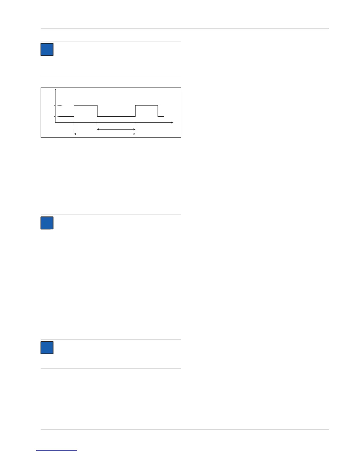
The dynamic signal type is a square wave signal with
the following characteristics:
NOTICE
The maintenance current can only be set if the
maintenance signal has been set to static. This function
is not available otherwise.
NOTICE
Alarms in the central controller may be triggered by
these functions! If necessary, the alarms in the central
controller must be disabled beforehand.