8 Dräger Polytron 8000
Installation
3.4 Mechanical installation
z Use the supplied drilling template for mounting on a wall.
z The mounting surface should be even and free of
sharp edges.
z Dräger recommends using M6 Allen bolts.
z The openings must be readily accessible to the surrounding
atmosphere.
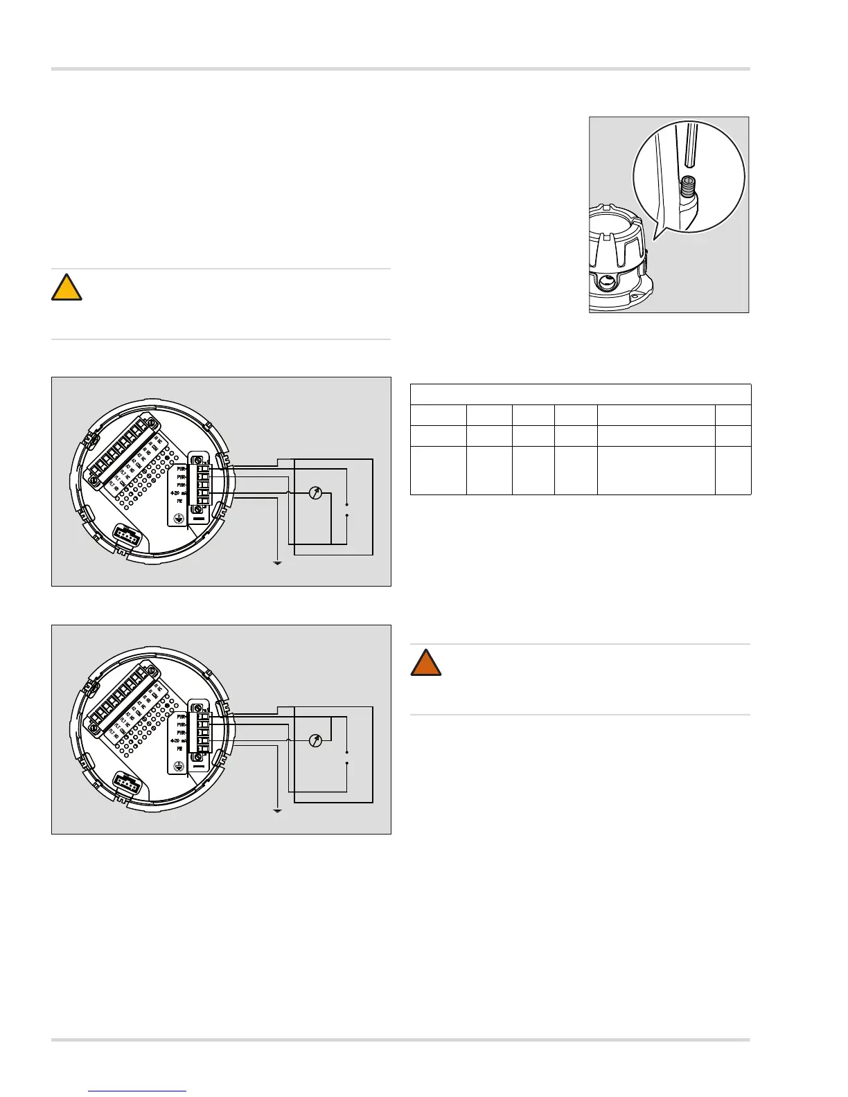
3.5 Electrical installation without e-Box
Connection diagram for operation as a current source
Connection diagram for operation as a current sink
3.5.1 Power and signal cables
1. Release the set screw and
unscrew the housing cover
from the device.
2. Lift the handle and remove
the enclosure with the main
electronics.
3. Connect the device
electrically to the protective
ground.
4. Turn over the main
electronics and disconnect
the 5-way plug.
5. Connect the three cables for
the power supply and the
signal to the corresponding
terminals (see following
table of connections for the 5-way plug).
Connections for 5-way plug (power supply and signal):
6. For operation without a central controller: connect Terminal 3
to Terminal 4.
7. Fit the plug back in the socket and tighten the screws.
8. The screen of the cable must only be connected to the
control unit.
9. Insert the main electronics back in the housing.
10. Screw the cover on again and tighten the set screw.
3.5.2 Version with relays
When the relay module is fitted, the wires for the alarm device
are connected to the 9-way plug.
1. Disconnect the 9-way plug on the rear of the main electronics.
2. Connect the wires for Alarm Relay 1, Alarm Relay 2 and the
Fault relay to the corresponding terminals, (see following
table of connections for the 9-way plug).
3. The relays are energized when the default settings are used
and in the measurement mode. This insures "fail-safe"
operation. The terminal assignments in the connection table
below apply when the default settings are used and when in
measuring mode (see chapter 4.6 on page 14).
4. Fit the plug back in the socket and tighten the screws.
5. Fit the enclosed protective cover over the plug and secure
it with cable ties if necessary.
CAUTION
First connect the cables for the relays and make
the connections to the sensor before connecting the
device to the power supply.