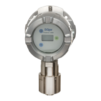
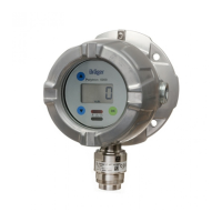
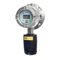
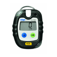
What to do if Sensor warm-up phase has not ended yet in Drager Measuring Instruments?
- SSandra HarrisSep 10, 2025
Wait until the sensor has warmed up.
What to do if Sensor warm-up phase has not ended yet in Drager Measuring Instruments?
Wait until the sensor has warmed up.
What to do if alarms disabled in Drager Measuring Instruments?
Enable the alarms.
What to do if PIR 7000/7200 optics dirty in Drager Measuring Instruments?
Clean the PIR 7000/7200 optics.
What to do if I have communications fault in Drager Measuring Instruments?
Check contact with PIR 7000/7200.
What to do if I have faulty zero-point in Drager Measuring Instruments?
Perform zero-point calibration.
What to do if I have faulty span calibration in Drager Measuring Instruments?
Perform a new span calibration.
What to do if Calibration interval expired in Drager Measuring Instruments?
Recalibrate the device.
What to do if SW dongle has been removed without logging out in Drager Measuring Instruments?
Disable the SW dongle.
What to do if Autocalibration not possible with PIR 7200 in Drager Measuring Instruments?
Perform a new zero-point and span calibration.
What to do if I have device fault, 4 - 20 mA PIR 7000/7200 in Drager Measuring Instruments?
Check the 4-20 mA connection on the PIR 7000/7200.
User must follow instructions, understand them, and use the product only as intended.
Use in hazardous areas requires adherence to specific regulations and approvals.
Explains icons like WARNING, CAUTION, and NOTICE for user awareness.
Electrical connections to non-listed devices require expert consultation.
Overview of explosion-proof devices and those with an e-Box, detailing components.
Describes the device's operation, power supply, display, LEDs, and analog/HART signals.
Specifies the device is for continuous monitoring of hydrocarbons/CO2 in potentially explosive atmospheres.
Details hazardous area classifications (zones/divisions) and temperature requirements.
Lists relevant certifications and markings for hazardous locations.
Explains how to interpret the device's serial number and manufacturing date.
Crucial factors for selecting a mounting location, including rules and environmental influences.
Details voltage, temperature, and positioning restrictions for proper installation.
Specifies impedance ranges for HART communication and multidrop operation.
Guidelines for mounting the device, including surface requirements and spacing.
Step-by-step guide for connecting power and signal cables to the 5-way plug.
Instructions for wiring alarm devices to the 9-way plug for relay modules.
Information on installing sensors remotely from the device electronics.
Guidance on installing the e-Box according to its specific instructions.
Details on connecting the device to control units like Regard or QuadGard.
Using an IR connection kit for PC communication with the device.
Overview of the software for displaying info, editing settings, and reading memory.
Instructions on installing various software dongles for enhanced functionality.
Explains basic operation, including menu navigation using the magnetic wand and symbols.
Details on the LCD display, status LEDs, and symbols indicating measurement status.
How to access device information like SW version, part number, and sensor details.
Explains symbols indicating device state like warnings, errors, maintenance, and range exceedance.
Describes the meaning of the red, yellow, and green LEDs and their associated states.
Accessing status and device settings without a password.
How to enter password-protected menus for configuration and calibration.
The normal operating state where gas concentration is displayed and the green LED is active.
Explains the 4-20 mA output signal, its proportionality to gas concentration, and NAMUR NE43 compliance.
General guidelines for calibrating the device, including warm-up and accessory use.
Step-by-step process for performing zero calibration using ambient air or calibration gas.
Procedure for performing span calibration with specific calibration gases and concentrations.
Details on enabling and performing automatic calibration sequences.
Displaying warning messages, fault messages, device codes, and installed modules.
Retrieving calibration data, including last and next calibration dates.
Querying datalogger status and displaying graphs of measured values.
Protecting configuration against unauthorized changes using a password.
Configuring alarm thresholds, relay behavior, and LED indications.
Setting passwords for calibration and general settings.
Adjusting the device's internal date and time settings.
Selecting the preferred language for the device display.
Assigning a specific function to the device's function key.
Reverting all device parameters to their default factory configurations.
Instructions for deactivating software dongles before removal or in case of faults.
Adjusting display contrast and choosing between standard or non-display modes.
Configuring communication interface parameters like HART and Profibus.
Setting fault current, warning signals, and warning intervals for the analog output.
Performing tests on the analog interface by setting specific currents for fault, warning, maintenance, or beam block.
Configuring sensor parameters like auto-calibration, tests, lock, and gas type.
Enabling or disabling the auto-calibration function available in the Calibration menu.
Settings related to the sensor self-test functionality.
Enabling or disabling continuous sensor self-checks for reliable operation.
Activating or deactivating the sensor interlock to control sensor type acceptance.
Selecting the specific sensor type (e.g., PIR 7000/7200) for device configuration.
Configuring gas type, measuring range, and units for accurate measurements.
Configuring datalogger functions like switching on/off and setting sampling intervals.
Enabling or disabling the datalogger's data recording function.
Choosing between overwriting old data or holding storage when capacity is reached.
Function to erase all stored data from the datalogger.
A table listing fault numbers, their causes, and recommended remedies.
A table listing warning numbers, their causes, and recommended remedies.
Specifies intervals for checks during commissioning, every 6 months, and as required.
Step-by-step instructions for replacing the sensor, including pre-checks.
Procedure for replacing the main electronic components of the device.
Guidelines for the proper disposal of electrical and electronic equipment according to EU regulations.
Lists substances, CAS numbers, and gas codes for the Type 334 gas library.
Lists substances, CAS numbers, and gas codes for the Type 340 gas library.
Details on analog output, current values for different states, and supply voltage.
Information on protection class and dimensions of the device housing.
Specifies the physical size of the device variants.
Weights of the device variants with and without e-Box, in aluminum and stainless steel.
Specifications for the device's back-lit LCD display resolution.
Specifies operating conditions like pressure, humidity, and temperature ranges.
Torque specifications for housing cover, sensors, blanking plugs, cable entry, and e-Box.
Torque and cable size requirements for field wiring terminals.
Lists unalterable and alterable factory default settings for various parameters.
Catalog numbers for various configurations of the Polytron 8700 Type 334.
Catalog numbers for various configurations of the Polytron 8700 Type 340.
Catalog numbers for various configurations of the Polytron 8720.
Order numbers for PIR sensors used with remote versions of the device.
Order numbers for replacement sensors for non-remote device versions.
Order numbers for various accessories like junction boxes and mounting kits.
Order numbers for accessories specific to PIR 7000/7200 sensors.
Order numbers for common replacement parts like cable bushings and hardware sets.
| Device Type | Gas detector |
|---|---|
| Measurement Principle | Electrochemical, catalytic, infrared |
| Gas Types | Combustible gases, toxic gases, oxygen |
| Output | 4 to 20 mA |
| Power Supply | 24 V DC |
| Operating Temperature | -40 to +65 °C |
| Humidity | 0-95% RH non-condensing |
| Protection Class | IP66/67 |
| Approvals | ATEX, IECEx, UL, CSA |
| Display | LCD |
| Housing Material | Polycarbonate, stainless steel |

