
C
Carol PerkinsAug 3, 2025
How to resolve zero calibration failed on Dräger Measuring Instruments?
- CCaitlin JohnsonAug 3, 2025
If the Dräger Measuring Instruments indicates 'Zero calibration failed', you should calibrate the sensor.
How to resolve zero calibration failed on Dräger Measuring Instruments?
If the Dräger Measuring Instruments indicates 'Zero calibration failed', you should calibrate the sensor.
How to resolve span calibration failed on Dräger Measuring Instruments?
If the Dräger Measuring Instruments indicates 'Span calibration failed', you should calibrate the sensor.
How to fix 'Please connect sensor' on Dräger Measuring Instruments?
If the Dräger Measuring Instruments display 'Please connect sensor', remove power, attach the sensor, and then reapply power.
What to do if Dräger Measuring Instruments show sensor failure?
If the Dräger Measuring Instruments indicates a sensor failure, remove power, reconnect or replace the sensor, and then reapply power.
How to troubleshoot 4-20 output error on Dräger Measuring Instruments?
If your Dräger Measuring Instruments display a '4-20 output error', remove power, check the field wiring from the Polytron 5000 to the control system, and then reapply power.
Essential safety precautions and general statements for proper equipment use.
Explains the meaning of DANGER, WARNING, CAUTION, and NOTICE icons used throughout the manual.
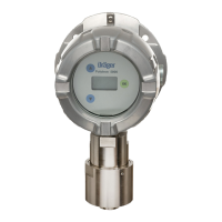
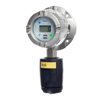
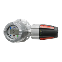
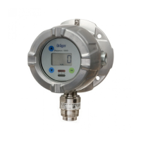
Visual breakdown of the explosion-proof instrument and its main components.
Defines the operational scope, hazardous area classifications, and conditions for the instrument.
Details the instrument's power, display, output signal, and user interface for navigation.
Steps and critical factors for selecting an optimal installation site and its limitations.
Wiring procedures for instruments without an explosion-proof enclosure (e-box).
Wiring instructions for optional relay and remote sensor configurations.
Two-step process for installing the instrument with an explosion-proof enclosure (e-box).
Instructions for connecting field wires to the instrument terminals.
Specific wiring instructions for multi-function instrument versions.
Procedure for securing the main instrument enclosure to the e-box.
Connecting internal instrument wiring to the e-box interface PCB.
Connecting to controllers and indicators for normal operation.
How to navigate menus, use the password, and change parameters.
Procedures for zero/span adjustment, alarm configuration, and testing.
Configuring alarm latching, acknowledgment, relay energization, and gas category.
DSIR calibration, signal settings, sensor selection, and LCD control.
General calibration process and specific steps for zero and span calibration.
List of error/warning messages, their meaning, and recommended remedies.
Instructions for safely replacing the sensor and main electronics.
Default values for settings adjustable via the instrument menu.
Description of fixed settings and the behavior of alarm LEDs.
Explanation of heat-of-combustion (DD/LC) and infrared (DSIR) sensor principles.
Substances affecting sensors and guidelines for instrument disposal.
Details on safety approvals, marking, and signal transmission standards.
Information on voltage, in-rush current, tightening torques, and wire sizes.
Enclosure details, dimensions, weight, and environmental operating limits.
List of available detector and transmitter part numbers.
Part numbers for remote sensing heads, replacement sensors, and accessories.
List of common spare parts with their respective part numbers.
| Brand | Dräger |
|---|---|
| Model | Polytron 5200 |
| Category | Measuring Instruments |
| Language | English |