EasyManua.ls Logo

Dräger Polytron 5100 - User Manual

Dräger Polytron 5100
30 pages
Print Icon
To Next Page IconTo Next Page
Loading...
WARNING
Strictly follow the Instructions for Use.
The user must fully understand and strictly observe the
instructions. Use the product only for the purposes specified
in the Intended use section of this document.
!
Dräger Polytron 5100
Instructions for Use
i
www.norrscope.com

Table of Contents

Question and Answer IconNeed help?

Do you have a question about the Dräger Polytron 5100 and is the answer not in the manual?

Summary

For Your Safety

General Safety Statements

Provides essential safety guidelines for using the Dräger Polytron 5100 instrument and its components.

Definition of Alert Icons

Explains the meaning of hazard alert icons (DANGER, WARNING, CAUTION, NOTICE) used in the document.

Product Description

Product Overview

Details the components of the Dräger Polytron 5100, including explosion-proof and increased safety instrument types.

Intended Use and Operating Area

Specifies the intended application, hazardous area classification (zones/divisions), and operating conditions for the instrument.

Installation Procedures

General Information for Installation

Covers key considerations for selecting installation sites and ensuring system performance and effectiveness.

Installation Restrictions

Outlines limitations and requirements for power supply, cable specifications, and environmental exposure.

Mechanical Installation

Provides guidance on mounting the instrument on a flat surface, ensuring accessibility and unobstructed sensor view.

Electrical Installation without Docking Station

Details power and signal wiring, including 2-wire/3-wire configurations, and relay options.

Electrical Installation with Docking Station

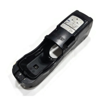
Describes the two-step process for mounting and connecting the Docking Station and main instrument.

Installing the Sensor

Step-by-step instructions for correctly installing the EC sensing head into the instrument or sensing head housing.

Connecting the EC Sensing Head Remote

Covers mounting kits, sensor installation, and connecting the remote EC sensing head to the Polytron 5100.

Operation of the Dräger Polytron 5100

Normal Operation and Display

Details the start-up sequence, warm-up period, and normal display and LED indications during operation.

Analog Signals

Explains the analog output signal (4-20 mA) proportional to the detected gas concentration.

Display and LED Symbols

Describes the meaning of display segments and LED indicators for normal operation, faults, and alarms.

Menu Navigation

Guides users on navigating the instrument's menu using a magnetic wand for configuration and parameter changes.

Menu Overview and Functions

Provides a flowchart of menu options and describes key functions like zero adjustment, span adjustment, and relay tests.

Maintenance and Calibration

Maintenance Intervals

Defines recommended inspection and check intervals for commissioning, every 6 months, and on demand sensor changes.

Calibration Procedures

Details the general procedure for calibration, including zero and span calibration, and warnings for proper execution.

Zero Calibration

Step-by-step guide for performing zero calibration using ambient air or nitrogen, ensuring correct zero point adjustment.

Span Calibration

Instructions for span calibration using calibration gas, adjusting sensitivity to match known concentration.

Troubleshooting Faults and Warnings

Lists common error and warning messages, their causes, and recommended remedies for the instrument.

Replacing the Sensor

Provides instructions for safely replacing the sensor, including necessary checks and potential factory default loading.

Replacing the Main Electronics

Details the procedure for replacing the main electronics, including power disconnection and parameter checks.

Cleaning the Instrument

Guidelines for cleaning the instrument using a soft cloth, water, and mild detergent.

Technical Specifications

Approvals and Marking

Lists safety approvals (ATEX, IECEx, UL) and explains the serial number key for determining the manufacturing year.

Signal Transmission and Power Supply

Details analog output signal ranges, power supply requirements, and cable specifications.

Physical and Environmental Specifications

Provides dimensions, weight, enclosure details, and environmental operating/storage conditions.

Tightening Torque and Wiring Terminals

Provides torque values for instrument threads and field wiring terminals for proper installation.

Ordering Information

Dräger Polytron 5100 Models

Lists available models of the Dräger Polytron 5100 gas detection instrument with their corresponding part numbers.

Docking Station Options

Details the available docking station versions, including power-only and power-and-relay configurations.

Accessories and Spare Parts

Lists various accessories and common spare parts available for the Dräger Polytron 5100.

Declaration of Conformity

EC Declaration of Conformity

States the product's compliance with EC directives (ATEX, EMC, Low Voltage) and lists applicable standards.

Overview

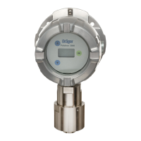
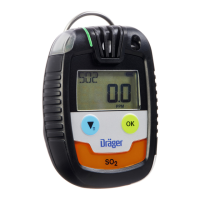
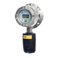
The Dräger Polytron 5100 is an explosion-proof instrument designed for the continuous monitoring of toxic gases and oxygen in ambient air. It is housed in a rugged stainless steel or aluminum enclosure, making it suitable for both indoor and outdoor applications.

Function Description:

The Polytron 5100 operates by measuring the partial pressure of gases using electrochemical sensors. The monitored ambient air diffuses through a membrane into a liquid electrolyte within the sensor. An electronic potentiostat circuit maintains a constant electrical voltage between the measuring electrode and reference electrode. The gas, selected to suit the monitoring requirements, is electrochemically transformed on the measuring electrode, generating a current proportional to the gas concentration. Simultaneously, oxygen from the ambient air reacts at the counter-electrode. This current is then electronically amplified, digitized, and corrected for various parameters, including ambient temperature.

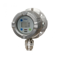
The instrument can be connected to a Dräger monitoring system or a Programmable Logic Controller (PLC) via a sealed conduit or approved cable gland. With an optional alarm relay configuration, it can also function as a stand-alone unit, providing local alarm signaling. It is designed for permanent installation in hazardous, classified areas (Zone 1 or 2, Class I or II, Div. 1 or 2) with specific temperature ranges (T4 or T6) and gas/dust groups (IIA, IIB, IIC or A, B, C, D, E, F, G).

The device is powered by 10 to 30 VDC (or 18 to 30 VDC for 2-wire configuration). Gas concentrations, status messages, and menu choices are displayed on a back-lit 4-digit LC-display and three colored LEDs. The measured gas concentration is converted to a 4 to 20 mA analog output signal per NAMUR recommendation NE43. It supports both 2-wire and 3-wire configurations, though certain features like the back-lit display or relays are not supported in 2-wire mode due to power consumption.

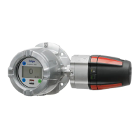
Navigation through the menu is performed non-intrusively by tapping a magnetic wand on the glass at the appropriate indicator. This allows for configuration, calibration, and maintenance without declassifying the area.

Important Technical Specifications:

  • Enclosure Material: Copper-free aluminum or 316 stainless steel.
  • Enclosure Protection: NEMA 4X and IP 65/66/67.
  • Display: 4-digit, 9-segment, back-lit LCD.
  • Dimensions (LxWxD, approx.):
    • Without Docking Station: 11.3" x 5.8" x 5.1" (285 x 150 x 130 mm)
    • With Docking Station: 11.5" x 7.1" x 7.4" (295 x 180 x 190 mm)
  • Weight (approx.):
    • Without Docking Station: Aluminum 4.9 lbs. (2.2 kg), Stainless Steel 316 8.8 lbs. (3.6 kg)
    • With Docking Station: Aluminum 7.7 lbs. (3.5 kg), Stainless Steel 316 11.9 lbs. (5.4 kg)
  • Operating Voltage:
    • 3-wire: 10 to 30 VDC (Class 2 power supply)
    • 2-wire: 18 to 30 VDC (Class 2 power supply)
  • Operating Current (max.):
    • Without relay, non-remote sensor: 80 mA at 24 V
    • With relay, remote sensor: 100 mA at 24 V
  • Cable Specification: 2-core or 3-core shielded cable (min. 18 AWG / 0.75 mm² at 230 V~ for field wiring).
  • Relay Rating (optional): SPDT, 0.1 A to 5 A at 230 V~, 50-60 Hz; 0.1 A to 5 A at 30 V resistive load; secured with a 5 A fuse.
  • Environmental Parameters:
    • Pressure: 20.7 to 38.4 in. of Hg (700 to 1300 hPa)
    • Humidity: 0% to 100% RH, non-condensing
    • Temperature: -40 to +149 °F (-40 to +65 °C)
    • Storage Temperature: -4 to +149 °F (-20 to +65 °C)
  • Analog Output: 4 to 20 mA (normal operation), 3.8 to 4 mA (drift below zero), 20 to 20.5 mA (measuring range exceeded), ≤ 1.2 mA (instrument fault 3-wire), ≤ 3 mA (instrument fault 2-wire), > 21 mA (fault on analog interface), 3.4 mA steady or 1 Hz modulation between 3 and 5 mA (maintenance signal).

Usage Features:

  • Menu Navigation: Intuitive menu system accessed via a magnetic wand, allowing users to scroll through selections and confirm choices.
  • Password Protection: Optional 4-digit password (0000-9999) to restrict access to menu settings.
  • Parameter Adjustment: Easy modification of numerical parameters and selection from preset choices using the magnetic wand.
  • Alarm Configuration:
    • A1/A2 Set Points: Configurable alarm levels for Alarm 1 (A1) and Alarm 2 (A2).
    • Rising/Falling Gas Concentration: Alarms can be triggered by either rising or falling gas concentrations.
    • Latching/Non-Latching: Alarms can be set to latch (remain active until acknowledged, even if gas concentration drops) or non-latching (clear when gas concentration no longer meets alarm condition).
    • Acknowledgeable/Non-Acknowledgeable: Alarms can be set to be acknowledgeable (relay can be reset before alarm condition clears) or non-acknowledgeable (relay cannot be reset until alarm condition clears).
    • Relay Energization: A1 and A2 alarm relays can be configured as energized ON (fail-safe) or OFF. The fault relay is always energized ON (fail-safe).
  • Maintenance Signal: User-selectable maintenance signal (steady 3.4 mA or oscillating 3 to 5 mA) transmitted on the analog output when the menu is accessed.
  • LCD On/Off: Option to turn off the LCD during normal operation, effectively making it a non-display instrument. The LCD automatically activates during alarms or faults.
  • Fault Relay Blinking/Steady: Controls the fault relay behavior during warm-up (pulsing or steady).
  • 2-wire or 3-wire Configuration: Allows selection of operation mode, disabling power-consuming options in 2-wire mode (current source, back-lit display, remote sensor, relays, LEDs).
  • 4 mA/20 mA Offset: Functions to add an offset to the analog output for calibration with central controllers.
  • Diagnostic Scan: Displays error codes to assist in troubleshooting.

Maintenance Features:

  • Maintenance Intervals:
    • During Commissioning: Check calibration, signal transmission, LEDs, and alarm device triggering.
    • Every 6 Months: Inspection by trained service personnel, check signal transmission, LEDs, and alarm device triggering. Maintenance intervals may be shortened based on safety and application conditions. Dräger recommends a service contract.
    • On Demand: Sensor replacement as needed.
  • Calibration:
    • Zero Calibration: Adjusts the zero reference point of the sensor. Can use ambient air (if known to be free of target gas) or nitrogen/synthetic air.
    • Span Calibration: Adjusts sensor sensitivity to match a known concentration of applied calibration gas. Dräger recommends using target gas for calibration.
    • Calibration Adapter: Required for applying calibration gas.
    • Altitude Compensation: New span calibration recommended if altitude or ambient pressure changes significantly from factory settings (sea level).
  • Troubleshooting: Provides a list of display sequences, faults, causes, and remedies for common issues (e.g., sensor connection, firmware errors, calibration failures, supply voltage issues).
  • Sensor Replacement: Can be performed in hazardous areas without interrupting power supply. Requires loosening a set-screw, unscrewing a bayonet ring, and inserting a new sensor. All settings and parameters must be checked after replacement.
  • Main Electronics Replacement: Requires turning off power or declassifying the area. Involves removing the bezel, disconnecting connectors, replacing the main electronics, and reassembling. All settings and parameters must be checked, and the instrument calibrated after replacement.
  • Cleaning: The instrument can be cleaned with a soft cloth using water and a mild detergent, then rinsed with water.
  • Disposal: Electrical and electronic equipment must be disposed of according to EC Directive 2002/96/EC and national laws. Electrochemical sensors must be disposed of in accordance with their material safety data sheets.

Dräger Polytron 5100 Specifications

General IconGeneral
BrandDräger
ModelPolytron 5100
CategoryMeasuring Instruments
LanguageEnglish

Related product manuals