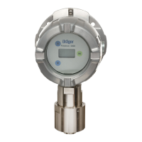
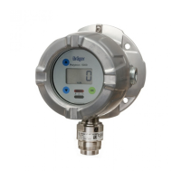
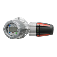
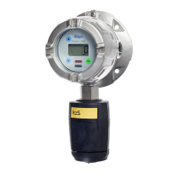
Dräger Polytron 5100 3
Contents
1 For your safety ........................................................ 5
1.1 General safety statements ........................................ 5
1.2 Definition of alert icons.............................................. 5
2 Description .............................................................. 6
2.1 Product overview....................................................... 6
2.1.1 Explosion proof instrument........................................ 6
2.1.2 Explosion proof instrument with increased safety
wiring compartment (Docking Station) ...................... 7
2.2 Intended use ............................................................. 8
2.3 Intended operating area and conditions.................... 8
2.4 Design....................................................................... 8
3 Installation ............................................................... 9
3.1 General information for installation ........................... 9
3.2 Installation restrictions............................................... 9
3.3 Mechanical installation............................................ 10
3.4 Electrical installation without Docking Station......... 10
3.4.1 Power and signal wiring .......................................... 10
3.4.2 Relay option............................................................ 10
3.5 Electrical installation with Docking Station.............. 11
3.5.1 Field wiring.............................................................. 11
3.6 Installing sensor ...................................................... 11
3.7 Installation of EC sensing head remote .................. 12
3.7.1 Wall or pipe mounting kit......................................... 12
3.7.2 Installing sensor ...................................................... 12
3.8 Connecting the EC sensing head remote
to Polytron 5100...................................................... 12
3.9
Connecting the instrument to a controller from Dräger
13
3.10 Connecting the instrument to a PC ......................... 13
3.11 PolySoft PC software (optional) .............................. 13
4 Operation ...............................................................13
4.1 Normal operation.....................................................13
4.1.1 Analog signals.........................................................13
4.1.2 The display and LEDs .............................................13
4.1.3 Segments of the display and LED symbols.............13
4.2 Menu navigation......................................................14
4.2.1 Password.................................................................14
4.2.2 Changing parameter values / status........................14
4.2.3 Exiting the menu......................................................14
4.3 Menu overview ........................................................15
4.3.1 -0- adj ......................................................................16
4.3.2 SPn adj....................................................................16
4.3.3 4-20 test ..................................................................16
4.3.4 Relay test ................................................................16
4.3.5 A1 set ......................................................................16
4.3.6 A2 set ......................................................................17
4.3.7 A1 rising / falling......................................................17
4.3.8 A2 rising / falling......................................................17
4.3.9 A1 latching...............................................................17
4.3.10 A2 latching...............................................................17
4.3.11 A1 acknowledgeable ...............................................17
4.3.12 A2 acknowledgeable ...............................................17
4.3.13 Explanation of combining latching and
acknowledgment of alarms......................................18
4.3.14 A1 energized ...........................................................18
4.3.15 A2 energized ...........................................................18
4.3.16 FSD set ...................................................................18
4.3.17 Cal set 3-5 or stdy ...................................................18
4.3.18 Pass set...................................................................18
4.3.19 LCD on/off ...............................................................18
4.3.20 Fault relay blinking / steady.....................................19
4.3.21 2-wire or 3-wire configuration..................................19
4.3.22 4 mA offset ..............................................................19
4.3.23 20 mA offset ............................................................19
4.3.24 Diag scan ................................................................19
 Loading...
