J
Jessica PhillipsSep 10, 2025
What to do if Sensor warm-up phase has not ended yet in Drager Measuring Instruments?
- KKenneth BoothSep 10, 2025
Wait until the sensor has warmed up.
What to do if Sensor warm-up phase has not ended yet in Drager Measuring Instruments?
Wait until the sensor has warmed up.
What to do if alarms disabled in Drager Measuring Instruments?
Enable the alarms.
What to do if PIR 7000/7200 optics dirty in Drager Measuring Instruments?
Clean the PIR 7000/7200 optics.
What to do if I have communications fault in Drager Measuring Instruments?
Check contact with PIR 7000/7200.
What to do if I have faulty zero-point in Drager Measuring Instruments?
Perform zero-point calibration.
What to do if I have faulty span calibration in Drager Measuring Instruments?
Perform a new span calibration.
What to do if Calibration interval expired in Drager Measuring Instruments?
Recalibrate the device.
What to do if SW dongle has been removed without logging out in Drager Measuring Instruments?
Disable the SW dongle.
What to do if Autocalibration not possible with PIR 7200 in Drager Measuring Instruments?
Perform a new zero-point and span calibration.
What to do if I have device fault, 4 - 20 mA PIR 7000/7200 in Drager Measuring Instruments?
Check the 4-20 mA connection on the PIR 7000/7200.
Essential guidelines for safe product operation and handling.
Explains the meaning of warning, caution, and notice icons used in the document.
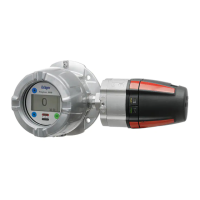
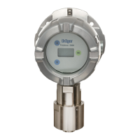
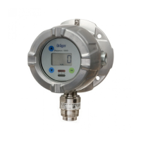
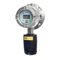
Explains how the device operates, its power supply, and display features.
Defines the product's intended application and suitable hazardous area classifications.
Covers crucial factors for selecting a mounting location and general installation.
Outlines limitations and conditions for installing the device correctly.
Details how to connect power and signal cables to the 5-way plug.
Explains basic operation, menu scrolling, and symbol meanings.
Describes how to modify parameter settings and confirm changes.
Outlines the importance of regular calibration and safety precautions.
Step-by-step guide for performing a zero point calibration using calibration gas.
Detailed steps for performing a span calibration with calibration gas.
Managing SIL lock and configuring basic device settings.
Setting up alarms, relay behavior, and alarm thresholds.
Setting HART polling address, unique identifier, tag, and REGARD protocol.
Configuring fault current, warning signal, and warning interval for the analog interface.
Enabling/disabling auto-calibration and sensor self-tests.
Lists fault numbers, their causes, and recommended remedies for device issues.
Lists warning numbers, their causes, and recommended remedies for device warnings.
Outlines required maintenance intervals and the procedure for changing the sensor.
| Type | Gas Detector |
|---|---|
| Signal Output | 4-20 mA |
| Housing Material | Stainless steel or aluminum |
| Approvals/Certifications | ATEX, IECEx, UL, CSA |
| Detection Principle | Infrared (IR) |
| Target Gas | Combustible gases |
| Measuring Range | 0-100% LEL (Lower Explosive Limit) |
| Operating Temperature | -40 to +65 °C |
| Operating Humidity | 0 to 95% RH (non-condensing) |
| Power Supply | 12-30 V DC |
| Display | LCD |
| Communication Interface | HART, Modbus |
| Output | Relays |
| Protection Class/Rating | IP66 |