Installation
Dräger Polytron 8700/8720 7
3 Installation
3.1 General information for the installation
The selection of a suitable mounting location is crucial for the
effectiveness and performance of the entire system.
Considerable thought must be given to every detail of
installation, particularly:
z the local and national rules and regulations for the
installation of gas monitoring systems,
z the applicable regulations for running and connecting
power and signal cables to gas monitoring systems,
z the full extent of environmental influences to which the
device will be subjected,
z the physical properties of the gases and vapors to be
measured,
z the details of the particular application (e.g., potential
leaks, air movements/flows, etc.),
z accessibility for required maintenance activities,
z the geometric of the accessories that are used with
the system,
z all other limiting factors and stipulations that may affect the
installation of the system.
z For installation without a conduit, an approved cable gland
(e.g. Hawke A501/421/A/¾" NPT or equivalent) must be
used (see chapter 13 on page 32). To increase the RF
interference immunity, it may be necessary to connect the
cable screen to the cable gland and to the control unit.
z The explosion proof enclosure has three ¾" NPT
connections, which can be used for field wiring, the direct
attachment of a sensor or wiring an external sensor. For the
correct tightening torques for cable bushings, plugs and
sensors, see chapter 13 on page 32.
z The secondary are supposed to be supplied from an
isolating source (does not apply to relay contacts).
z The optional e-Box has up to four 20 mm connections,
which can be used for field wiring or wiring an external
sensor. The permissible cable diameter is 7 to 12 mm.
z If the device is installed in locations where ambient
temperatures of over 55 °C prevail, appropriate cables
which are designed for use at temperatures of 25 °C above
the maximum ambient temperature must be used.
z Strip back the insulation on conductors by 5 to 7 mm.
z Connect the cable as shown in Chapter 3.5 on page 8
(shown here also with protective ground).
z The use of a mounting spacer (Order Number 68 12 617)
is recommended as a matter of principle if the device is to
be mounted on a wall or on a very uneven substrate.
z The connecting wires for the optional relay module must be
selected and fused according to the rated voltages,
currents and environmental conditions.
z When stranded conductors are used, an end ferrule must
also be used.
3.2 Restrictions on the installation
z The device requires a DC voltage between 10 and 30 V.
The minimum supply voltage of 10 V and the cross-section
of the conductors used determine the distance of the
device from the supply or the central controller
(see chapter 13 on page 32). The device is designed for
cables of sizes 12 to 24 AWG (0.2 to 2.5 mm
2
). A three-
wire, screened cable must be used as a minimum.
z The device must not be subjected to any radiant heat
(e.g. direct sunlight) as this may result in a temperature rise
above the specified thresholds (see chapter 13 on
page 32). The use of a reflective screen is recommended.
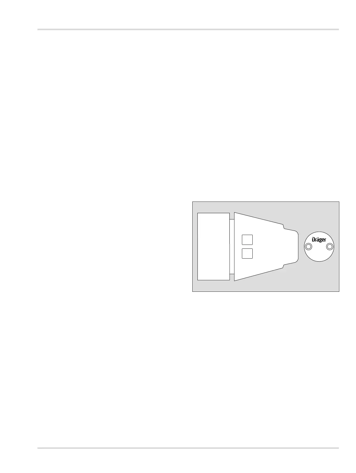
z If a splash guard (Order Number 68 11 911 or 68 11 912) is
used, it is essential to make sure that the LEDs on the
status display are aligned vertically and the "Dräger" logo
on the splash guard is aligned horizontally. A maximum
deviation of ±10 degrees from the horizontal position is
permissible. Greater deviations will increase the response
time (see Instructions for Use for the PIR 7000/7200).
z Observe the preferred position: The PIR 7000/7200 must
be aligned so that the lights on the status display are above
one another. At the same time, the "Dräger" lettering on the
splash guard must read horizontally. A deviation from the
horizontal of ±10° maximum is permissible.
z Any other alignment is only permissible if the PIR 7000/
7200 is used without a splash guard, e.g. applications in
exhaust ducts. When the sensor is fitted in an exhaust duct,
there is an increased risk that residues will form on the
optical surfaces.
z The housing is weather resistant and suitable for outdoor
applications. The use of the optional splash guard is
recommended to protect the sensor from water and dust.
z The device must be installed and operated in an
environment which conforms to the stated specifications
(see chapter 13 on page 32).
z To insure proper operation of the device, the impedance of
the 4 to 20 mA signal loop must not exceed 500 ohms.
Depending on the operating voltage and according to the
application (e.g. HART operation), certain minimum
impedances must be adhered to (see chapter 3.3 on
page 8). The conductors for the power supply must have
an adequately low resistance to insure the correct supply
voltage at the device.
00333300.eps
1