8 Dräger Polytron 8700/8720
Installation
3.3 Impedance range of the signal loop
Devices with a HART interface can be operated with HART
communication or in HART Multidrop mode.
3.4 Mechanical installation
z Use the supplied drilling template for mounting on a wall.
z The mounting surface should be even and free of
sharp edges.
z Dräger recommends using M6 Allen bolts.
z Take care that the conditions at the mounting location do
not result in the gas feed openings of the PIR 7000/7200
being covered or obstructed.
z The openings must be readily accessible to the
surrounding atmosphere.
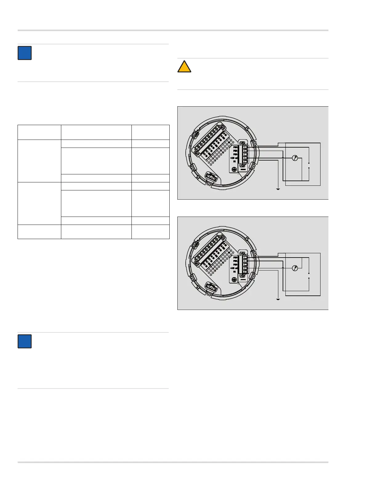
3.5 Electrical installation without e-Box
Connection diagram for operation as a current source
Connection diagram for operation as a current sink
NOTICE
A dust cap can be fitted to the cable entry of the device.
This cap is only used for transport purposes and must
be removed before the device is connected to a sealed
conduit.
Operating mode
Impedance range of the
signal loop
Supply
voltage range
Operation
without HART
communication
0 to 230 Ω at 10 V DC
Rising linearly with the
supply voltage from:
0 to 230 Ω at 10 V to
0 to 500 Ω at 16 V
10 to 18 V DC
0 to 500 Ω 18 to 30 V DC
Operation with
HART
communication
(HART mode)
230 to 270 Ω at 13 V DC
Rising linearly with the
supply voltage from:
230 to 270 Ω at 11 V to
230 to 500 Ω at 16 V
11 to 16 V DC
230 to 500 Ω 18 to 30 V DC
HART Multidrop
operation
230 to 500 Ω 10 to 30 V DC
NOTICE
There must be a free space of 5 cm next to the
PIR 7000/7200 to permit fitting/removal of the splash
guard and the later fitting of accessories.
To ensure an adequate distance between the
PIR 7000/7200 and the wall, use the mounting
spacer (Order Number 68 12 617).
i
i
i
i
CAUTION
First connect the cables for the relays and make
the connections to the sensor before connecting the
device to the power supply.
!