Operation
Dräger Polytron 5200 / Dräger Polytron 53X0 9
3.3 Electrical installation with e-box
Installing this configuration is a two step process.
First, the e-box is mounted and connected to the field wires.
Second, the main instrument enclosure with the electronics
and sensor is attached to the e-box.
The e-box can be pre-mounted, wired and sealed with the sup-
plied cover. Once the site is ready for commissioning, the
instrument is then hooked up to the e-box and taken into oper-
ation; avoiding that the instrument is damaged during the
construction phase.
The connection between the e-box and the main instrument is
realized via a ‘feed-through’. Depending on the instrument
selected, there are 3 types of feed-through.
{
3 wire for power (part number 4544182)
{
9 wire for power and relay (part number 4544169)
{
14 wire for power, relay and remote sensor (part
number 4544168)
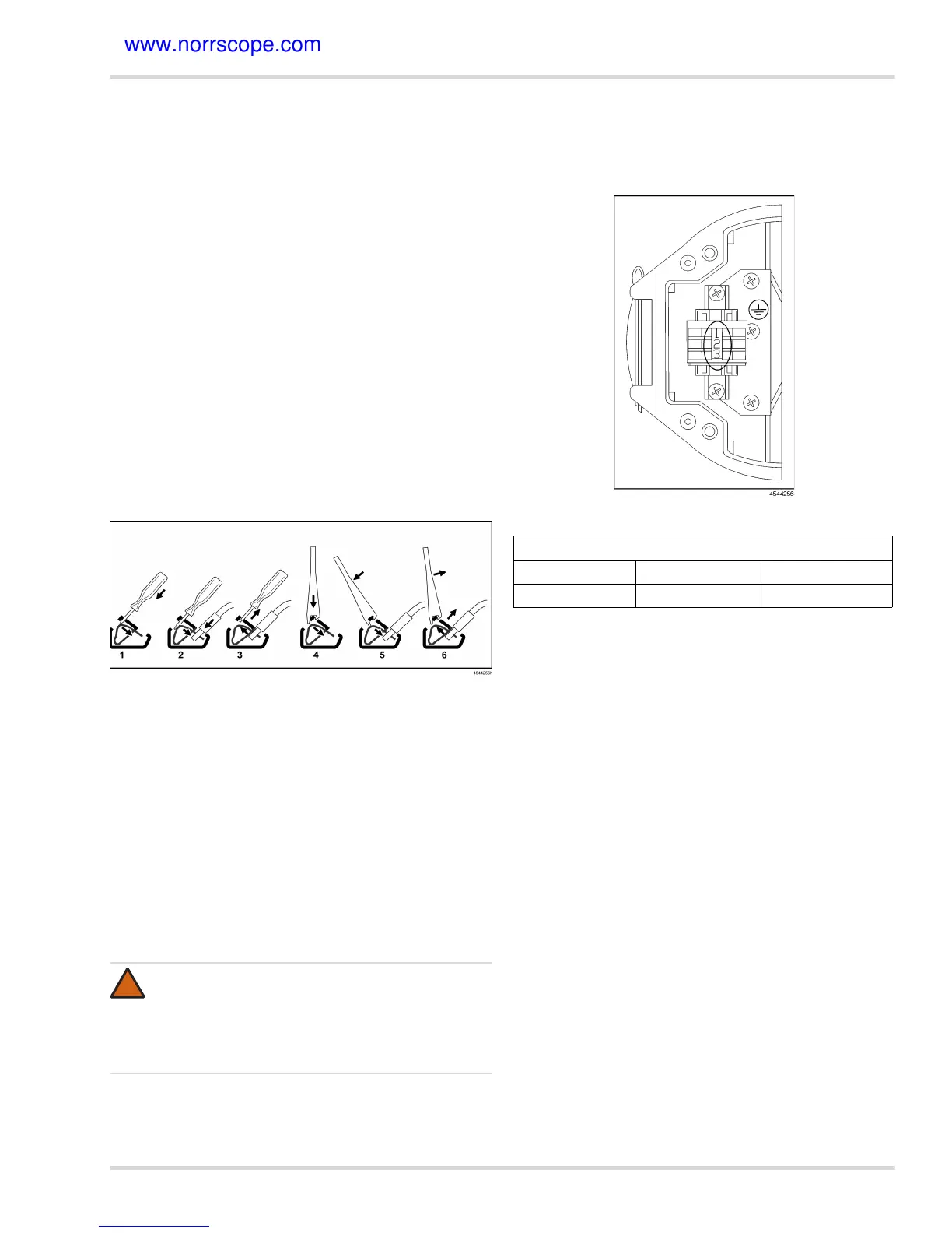
In some e-boxes, the field wires are terminated in spring clamp
terminals.
Screw driver or special tool
1. Insert screw driver (width 3 mm) into the spring clamp
terminal.
2. Press spring down to open the clamp in the lower part.
Insert stripped cable end or ferrule (for stranded wires) into
the lower part.
3. Remove screw driver. The electrical connection is ensured
via the constant pressure of the spring.
or
1. Insert special tool (part number 8318376) into the spring
clamp terminal.
2. Press spring down to open the clamp in the lower part.
Insert stripped cable end or ferrule (for stranded wires) into
the lower part.
3. Remove special tool. The electrical connection is ensured
via the constant pressure of the spring.
3.3.1 Field wiring
Connect all applicable field wires to the respective terminals.
3.3.2 Field wiring: power only version
WARNING
Bare cables must not stick out of the spring terminals.
The method of explosion protection during mainte-
nance is based on the condition that it is not possible
to contact bare cable parts by a probe of 2.5 mm diam-
eter (definition of IP 30).
!
Solid Oval (Power Only)
Terminal 1 (top) Terminal 2 Terminal 3
V + V - 4 to 20 mA Signal