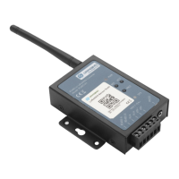
User Manual for LoRaWAN End Nodes - RS485-LN – RS485 to LoRaWAN Converter User Manual
Set Payload version
This is the first byte of the uplink payload. RS485-LN can connect to different sensors. User can set the PAYVER
field to tell server how to decode the current payload.
• AT Command:
AT+PAYVER:Set PAYVER field = 1
• Downlink Payload:
0xAE 01 --> Set PAYVER field = 0x01
0xAE 0F --> Set PAYVER field = 0x0F
Set RS485 Sampling Commands
AT+COMMANDx or AT+DATACUTx
These three commands are used to configure how the RS485-LN polling data from Modbus device. Detail of usage
please see : polling RS485 device.
• AT Command:
AT+COMMANDx:Configure RS485 read command to sensor.
AT+DATACUTx:Configure how to handle return from RS485 devices.
• Downlink Payload:
0xAF downlink command can be used to set AT+COMMANDx or AT+DATACUTx.
Note: if user use AT+COMMANDx to add a new command, he also need to send AT+DATACUTx downlink.
Format: AF MM NN LL XX XX XX XX YY
Where:
• MM: the ATCOMMAND or AT+DATACUT to be set. Value from 01 ~ 0F,
• NN: 0: no CRC; 1: add CRC-16/MODBUS ; 2: set the AT+DATACUT value.
• LL: The length of AT+COMMAND or AT+DATACUT command
• XX XX XX XX: AT+COMMAND or AT+DATACUT command
• YY: If YY=0, RS485-LN will execute the downlink command without uplink; if YY=1, RS485-LN will execute
an uplink after got this command.
Example:
AF 03 01 06 0A 05 00 04 00 01 00: Same as AT+COMMAND3=0A 05 00 04 00 01,1
AF 03 02 06100105 06 09 0A00: Same as AT+DATACUT3=16,1,5+6+9+10
AF 03 02 060B0205 07 08 0A00: Same as AT+DATACUT3=11,2,5~7+8~10
Page 25 / 38 - last modified by Bei Jinggeng on 2022/07/08 16:50

 Loading...