User Manual for LoRaWAN End Nodes - RS485-LN – RS485 to LoRaWAN Converter User Manual
AT+ADR=0 Set the Adaptive Data Rate Off
AT+DR=5 Set Data Rate
AT+TDC=60000 Set transmit interval to 60 seconds
AT+CHS=868400000 Set transmit frequency to 868.4Mhz
AT+RX2FQ=868400000 Set RX2Frequency to 868.4Mhz (according to the result from server)
AT+RX2DR=5 Set RX2DR to match the downlink DR from server. see below
AT+DADDR=26 01 1A F1 Set Device Address to 26 01 1A F1, this ID can be found in the LoRa Server
portal.
ATZ Reset MCU
Note:
1. Make sure the device is set to ABP mode in the IoT Server.
2. Make sure the LG01/02 gateway RX frequency is exactly the same as AT+CHS setting.
3. Make sure SF / bandwidth setting in LG01/LG02 match the settings of AT+DR. refer this link to see what DR
means.
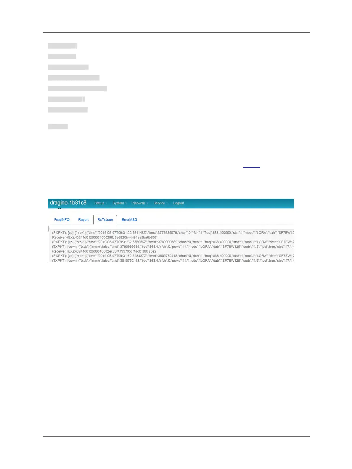
4. The command AT+RX2FQ and AT+RX2DR is to let downlink work. to set the correct parameters, user can
check the actually downlink parameters to be used. As below. Which shows the RX2FQ should use 868400000 and
RX2DR should be 5
6. FAQ
6.1 How to upgrade the image?
The RS485-LN LoRaWAN Controller is shipped with a 3.5mm cable, the cable is used to upload image to RS485-
LN to:
• Support new features
• For bug fix
• Change LoRaWAN bands.
Below shows the hardware connection for how to upload an image to RS485-LN:
Page 33 / 38 - last modified by Bei Jinggeng on 2022/07/08 16:50
 Loading...