User Manual for LoRaWAN End Nodes - RS485-LN – RS485 to LoRaWAN Converter User Manual
Downlink Command:
0xA6 aa bb cc same as AT+RXMODE=aa,(bb<<8 | cc)
Example:
The RS485-LN is set to AT+RXMODE=2,1000
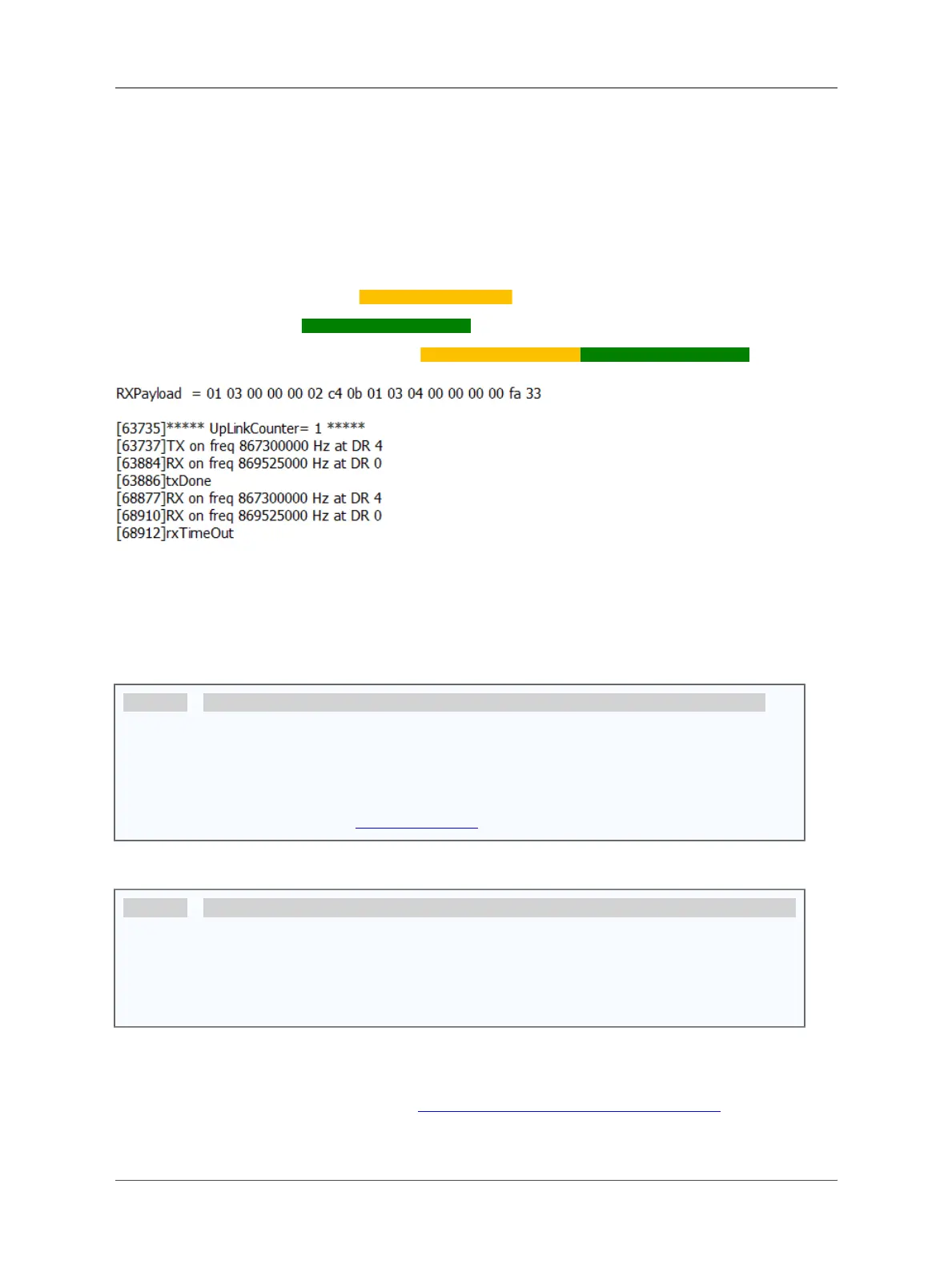
There is a two Modbus commands in the RS485 network as below:
The Modbus master send a command: 01 03 00 00 00 02 c4 0b
And Modbus slave reply with: 01 03 04 00 00 00 00 fa 33
RS485-LN will capture both and send the uplink: 01 03 00 00 00 02 c4 0b01 03 04 00 00 00 00 fa 33
Notice: Listening mode can work with the default polling mode of RS485-LN. When RS485-LN is in to send the
RS485 commands (from AT+COMMANDx), the listening mode will be interrupt for a while.
3.7 Buttons
Button Feature
ACT If RS485 joined in network, press this button for more than 1 second, RS485 will upload a packet,
and the SYS LED will give a Blue blink
RST Reboot RS485
PRO Use for upload image, see How to Update Image
3.8 LEDs
LEDs Feature
PWR Always on if there is power
SYS After device is powered on, the SYS will fast blinkin GREENfor 5 times, means RS485-LN start to join
LoRaWAN network. If join success, SYS will be on GREEN for 5 seconds.SYS will blink Blueon
every upload and blink Greenonce receive a downlink message.
4. Case Study
User can check this URL for some case studies: APP RS485 COMMUNICATE WITH SENSORS
Page 30 / 38 - last modified by Bei Jinggeng on 2022/07/08 16:50
 Loading...