29
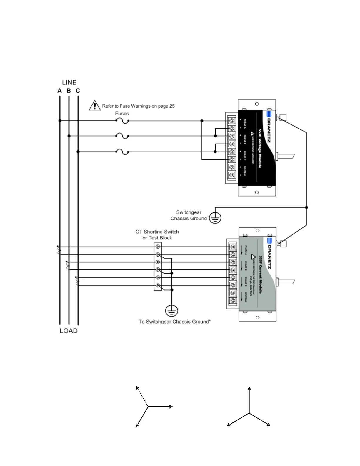
3 Phase (Floating or Grounded) Delta
In this connection, the instrument uses voltage channels A, B, and C as
differential inputs with channel A monitoring phase A-B, channel B
monitoring phase B-C, and channel C monitoring phase C-A. Current
inputs are connected to measure line currents A, B, and C.
CAUTION Connections must be performed in compliance with all
safety requirements applicable to your installation.
*NOTE Connections of the CT leg to ground is recommended,
but not required for proper operation.
Phasor Diagrams
V
A
V
B
0º
120 º
V
C
º
I
A
I
C
33 0
90º
I
B
210º
HDPQ-DN-MZP-104
 Loading...