Starting up
presetting of the function-switches
Measuring range
Switch 1
Switch 2 Switch 3
5 A OFF OFF OFF
10 A ON OFF OFF
20 A ON ON OFF
40 A ON ON ON
Switch 4
current monitoring window
Switch 5
alarm self-hold
Switch 6
Alarm output
OFF monitoring of the whole window not self-holding Alarm = “HIGH“ (24V)
ON monitoring of undercurrent only self-holding Alarm = “LOW“ (0V)
Switch 1,2 and 3 - current monitoring
First, set the appropriate measuring range for the anticipated operating current with the
slide switches. Select the smallest possible measuring range to obtain optimum current
measuring.
Example: heating current: 16A, measuring range 20A → Sw1=ON Sw2=ON Sw3= OFF.
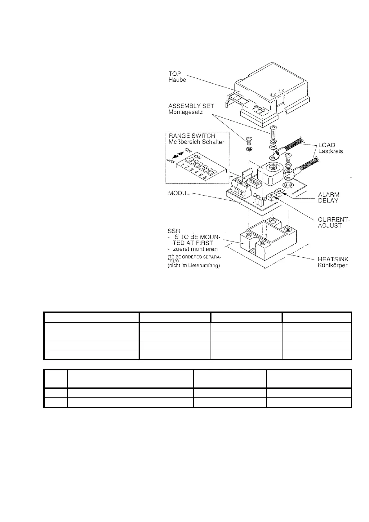
Assembly
instructions
The HCC-11 is mounted on the
solid-state relay, which is
already installed. The housing
cover is to be released by
slightly bending apart the lateral
retaining clips. The module is
mounted on the solid-state relay
and the electric load is
connected with the enclosed
assembly kits.
Important:
Before assembly, make sure
to check whether the inch or
metric-based assembly kit is
required.
Cable lugs must be attached to
the load connectors.
The electrical connections must
be made according to the wiring
diagram.
Assembly drawing