Switch 4 - Monitoring of the maximum current value
When using loads with a high inrush current, e.g. infra-red heaters and light bulbs, the
maximum current monitoring should be switched off (setting: Sw4 = ON).
Switch 5 - Self-holding of malfunction alarm
If an automatic reset of the malfunction alarm is not desired, then Sw5 should be set to ON.
Any further malfunction alarms can only then be reset by turning off the supply voltage.
Switch 6 - Inverted switching function of the alarm output
The switching function of the alarm-output is inverted by setting Sw6 to ON.
An activated malfunction alarm will then output a LOW-signal (=DC 0V).
This function, however, does not allow the parallel switching of multiple alarm outputs
to one collective alarm.
• Heating circuit monitoring without actual current value monitoring
If the heating circuit needs to be monitored only for interruption, short circuiting and SSR
malfunctions, select the smallest measuring range on the module (Sw1+2+3 = OFF; Sw4 = ON). The
“current adjust“ trimming resistor must be turned fully counter-clockwise. No further adjustment is
necessary. Current of less than 1,25A are evaluated as interruptions. A fault message is issued
without any delay.
• Fine adjustment to nominal current
First close the module with the hood and set “alarm delay“ to the maximum value.
Switch on the system; the “control signal“ and auxiliary “power supply“ must be present. The green
LED comes on to confirm the presence of the control signal and auxiliary power supply. Slowly adjust
the “current adjust“ trimmer for monitoring the setpoint until the yellow LED comes on. This setting
concludes the adjustment required for matching to the flowing nominal current.
Then set the alarm delay time (2 to 40 secs) to the system-specific value in order to
prevent false alarms.
• Operation of the HCC-11
During fault-free operation, the green and yellow LEDs both come on in time with the control-signal.
Current fluctuations of greater than ±2 % cause the yellow LED to go out. This does not have any
effect, however, as the current monitoring window is set to ±15 % of the nominal current.
If the nominal current moves outside the monitoring window, the red LED comes on after the delay
and the output signal is activated (according to Sw.6). If no self-hold is activated, the fault signal goes
out when the nominal current returns to within the window and when external faults have been
eliminated. Fuse and SSR malfunctions are indicated immediately.
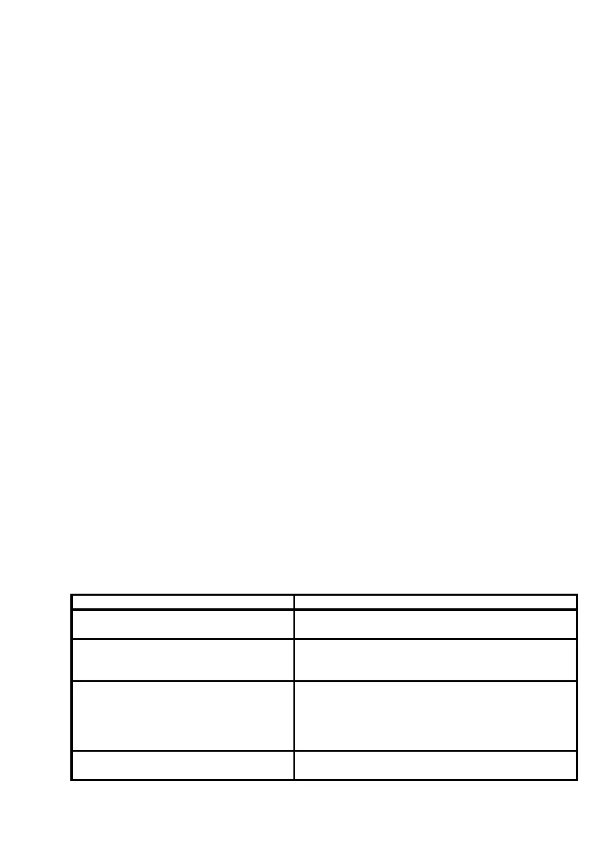
Troubleshooting
Check the position of the range switch.
Fault Cause
Green LED does not come on
• No auxiliary supply (or reversed polarity)
• No control signal
Current adjustment not possible,
yellow LED does not come on
• Load circuit interrupted
• No control signal
• Incorrect current range set
Red LED comes on
• Circuit or load interrupted
• Partial Load
• Fuse blown
• SSR malfunction
• Current outside monitoring window
Red LED comes on, no HIGH-signal at
output
• Short circuit or overload at output
• Sw6 = ON (inverted alarm-output)
 Loading...