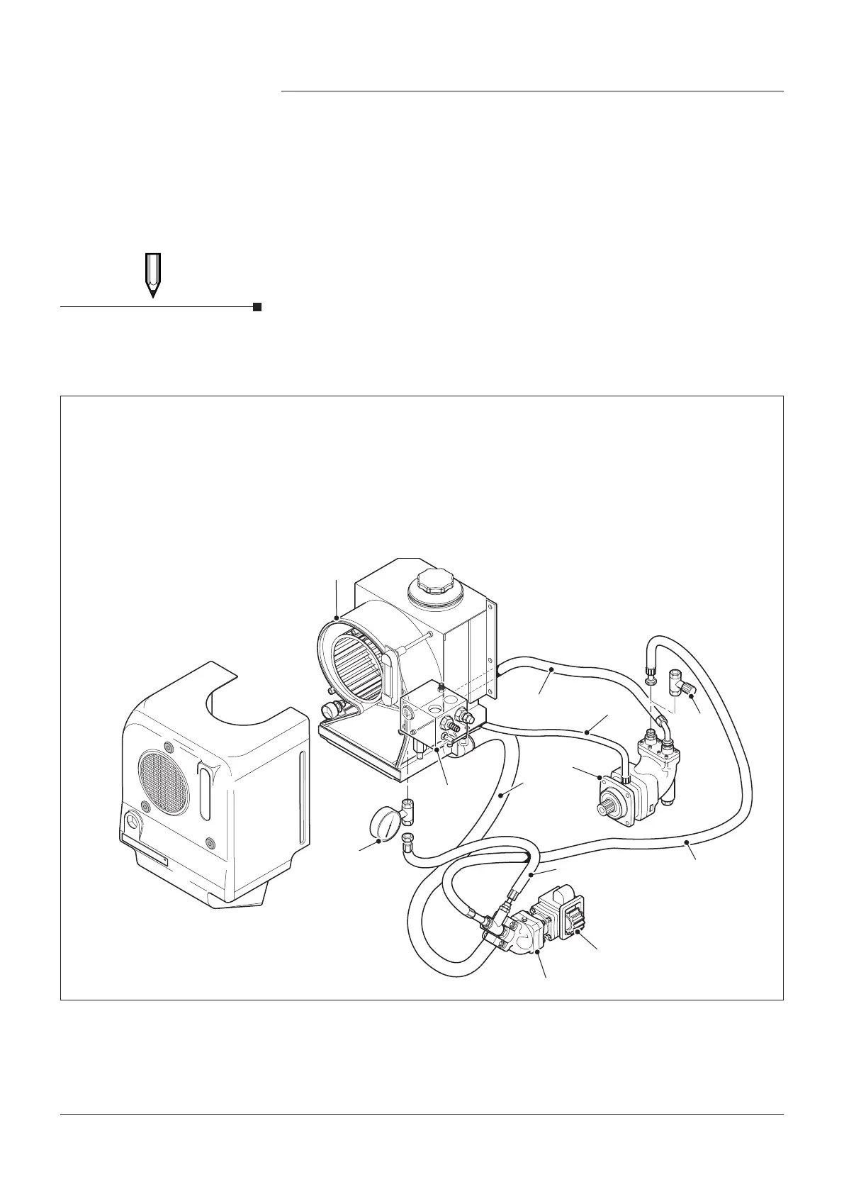
KEY
1. Hydrapak
2. Suction Line to Pump
3. Hydraulic Motor
4. Motor Case Drain Line
(CD)
5. Pressure Line to Motor
6. Hydraulic Motor
7. Power Take o
8. Pressure Line (P)
9. Return Line (R)
10. Polyhydron Block
Assembly
11. Pressure gauge
12. Throttle valve
3.7 Pressure Relief Valve
The working pressure of hydraulic drive systems is dependant on the
installation and the load upon the system.
Although the normal working pressure range of the Hydrapak is 80-200 bar
(LP) and 200-300 bar (HP version) the units are supplied with the relief valve
preset to allow operation up to 180 bar (LP) and 280 bar (HP version).
If there is a need to increase/decrease these settings up to the maximum
working pressure or reduce them to protect sensitive hydraulic equipment,
follow the instructions in section 3.8.
To set the relief valve, a pressure gauge and a throttle valve must be
connected into the pressure lines as shown in (Fig 7). Refer to Fig 8 for
Relief Valve setting.
For the best protection, the relief valve should be reset to the maximum
working pressure +30 bar on all hydraulic systems.
Installation
Fig. 7 Typical system layout
Setting/adjusting the relief
valve should only be carried
out by a competent person
with the correct equipment.
NOTE
Page 12
4991015005 Date:02/18
Hydrapak Installation, Operating & Maintenance Manual