3.8 Relief Valve Setting Procedure
After draining the system and inserting a throttle valve and pressure gauge
into the system (see g 7):-
1. With the throttle valve fully open, run the system under load at
normal operating speed and measure the normal working pressure.
2. Fully close the Throttle Valve to increase the pressure in the system.
The drive motor will stop and the relief valve will go on full by-pass.
3. Using a 17mm spanner, loosen the locking nut on the relief valve
adjusting screw (item 5).
4. Insert a 3/16” allen key (item4) into the adjusting screw (item
5) and rotate as shown in an anti-clockwise direction to increase the
by-pass pressure so that it is 30 bar above the normal working
pressure.(Fig 8).
5. Drain the system then remove throttle valve and gauge (Fig 7 Items
11 & 12).
Installation
At high operating pressure the
system will heat up rapidly.
Make adjustments quickly
then re-open the Throttle
Valve
CAUTION
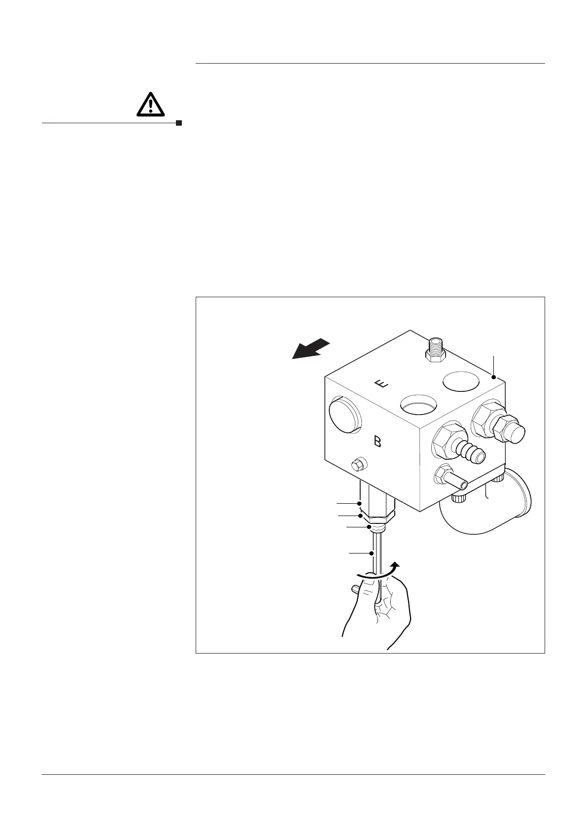
Fig. 8 Setting Relief Valve
2
To front of
Hydrapak
1
4
5
3
KEY
1. Relief Valve
2. Polyhydron
Block
3. 10mm Locking
Nut
4. 3/16” Allen key
5. Adjusting Screw
Page 13
4991015005 Date:02/18
Hydrapak Installation, Operating & Maintenance Manual