15
1.2 Rear Panel
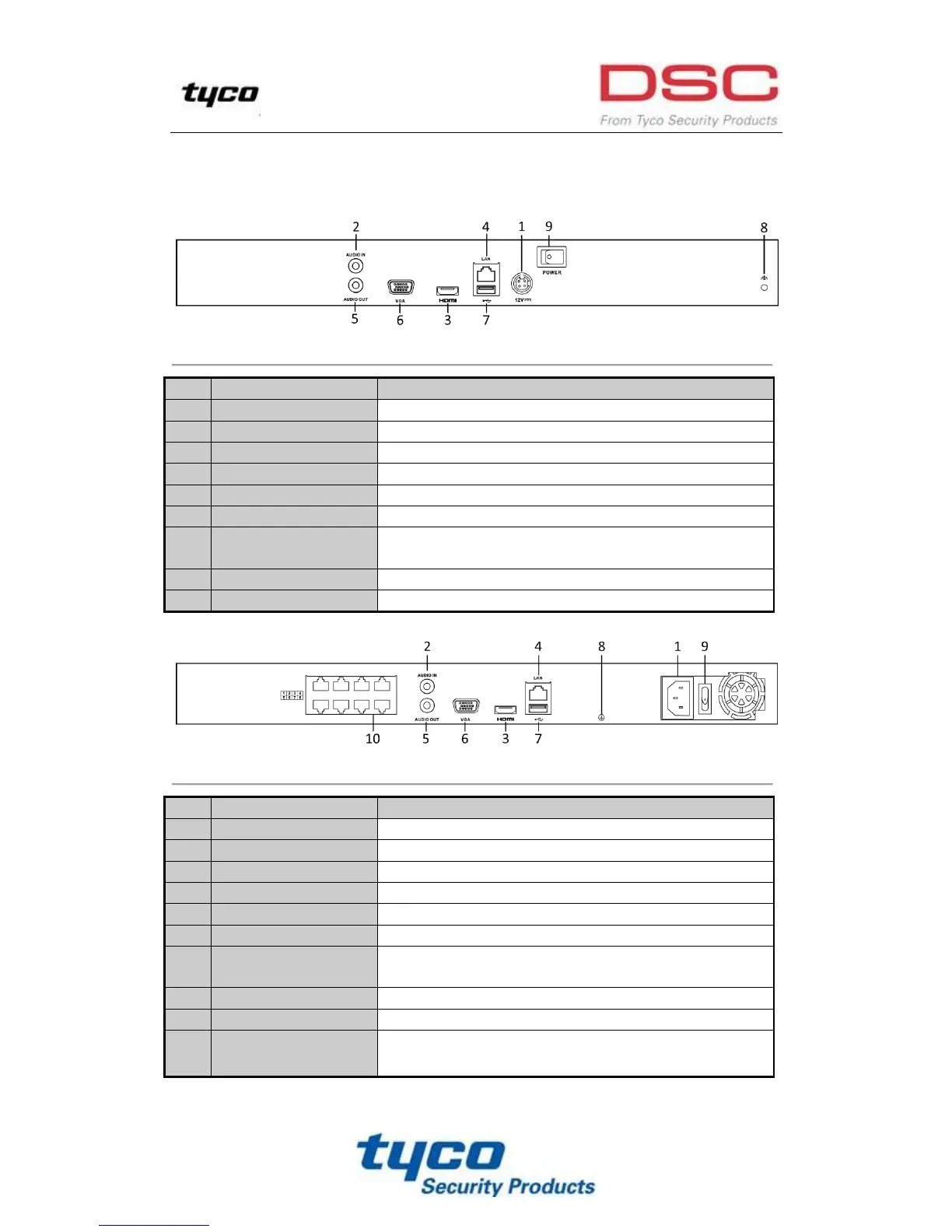
Figure 1. 4 DSC-N114-8/ DSC-N114-16
RCA connector for audio input.
HDMI
TM
video output connector.
1 10 /100 /1000 Mbps self-adaptive Ethernet interface
RCA connector for audio output.
DB9 connector for VGA output. Display local video output and menu.
Universal Serial Bus (USB) ports for additional devices such as USB
mouse and USB Hard Disk Drive (HDD).
Ground (needs to be connected when NVR starts up).
Switch for turning on/off the device.
Figure 1. 5 DSC-N114-8P/ DSC-N114-16P
RCA connector for audio input.
HDMI
TM
video output connector.
1 10 /100 /1000 Mbps self-adaptive Ethernet interface
RCA connector for audio output.
DB9 connector for VGA output. Display local video output and menu.
Universal Serial Bus (USB) ports for additional devices such as USB
mouse and USB Hard Disk Drive (HDD).
Ground (needs to be connected when NVR starts up).
Switch for turning on/off the device.
Network Interfaces with
PoE function
Network interfaces for the cameras and to provide power over Ethernet.